Mesaj Bırakın
Ürünlerimizle ilgileniyorsanız ve daha fazla bilgi edinmek istiyorsanız, lütfen buraya bir mesaj bırakın, en kısa sürede size cevap vereceğiz.

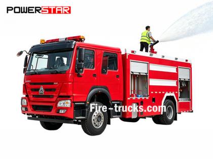
Isuzu İtfaiye Aracı 4HK1-TC Motor Bakım Kılavuzu, aynı zamanda Motor Tamir Kılavuzu olarak da adlandırılır. Isuzu itfaiye aracı veya Mühendislik kitabı Isuzu yangın söndürme aracı .
Isuzu İtfaiye Aracı 4HK1-TC motoru, güvenilirliği, dayanıklılığı ve yüksek verimliliğiyle bilinen, itfaiye araçlarında yaygın olarak kullanılan yüksek performanslı bir dizel motordur. Motorun uzun vadeli istikrarlı çalışmasını sağlamak için düzenli bakım ve onarım şarttır. Bu makale, bakım personelinin daha iyi anlamasına ve çalıştırmasına yardımcı olmak amacıyla Isuzu İtfaiye Aracı 4HK1-TC Motor Bakım Kılavuzunun ana içeriğini kısaca tanıtacaktır.
1. Motor Genel Bakışı
4HK1-TC motoru, 5,2 litrelik hacme ve 190 beygir maksimum güce sahip, sıralı 4 silindirli turboşarjlı bir dizel motordur. Motor, daha yüksek yakıt verimliliği ve daha düşük emisyonlar elde etmek için gelişmiş bir common rail yakıt enjeksiyon sistemi ve elektronik kontrol ünitesi (ECU) kullanmaktadır.
2. Günlük Bakım
Günlük bakım, motorun normal çalışmasının temelini oluşturur. Bakım kılavuzunda, yağ ve soğutma suyu seviyesi kontrolü, hava filtresi temizliği veya değişimi, yakıt filtresi değişimi vb. dahil olmak üzere günlük kontrol edilecek maddeler ayrıntılı olarak listelenmiştir. Ayrıca kılavuzda, genellikle her 5.000 kilometrede veya 6 ayda bir olmak üzere, motor yağı ve yağ filtresinin düzenli olarak değiştirilmesine ilişkin öneriler de yer almaktadır.
3. Arıza Teşhisi
Bakım kılavuzu, bakım personelinin sorunları hızlı bir şekilde tespit edip çözmesine yardımcı olmak için ayrıntılı bir arıza teşhis süreci içerir. Kılavuzda yaygın arıza kodları ve anlamları listelenir ve bunlara karşılık gelen çözümler sunulur. Örneğin, motor yetersiz güç üretiyorsa, kılavuz bakım personelini yakıt sistemi, turboşarj ve egzoz sistemi vb. kontrol etmeye yönlendirecektir.
4. Revizyon ve Parça Değişimi
Motor revizyonu veya parça değişimi gerektiren durumlarda, bakım kılavuzu ayrıntılı adımlar ve önlemler sunar. Örneğin, piston segmanları, supap kılavuzları ve yataklar gibi önemli bileşenlerin değiştirilmesi sırasında, kılavuz sökme ve takma adımlarının yanı sıra gerekli aletleri ve tork özelliklerini ayrıntılı olarak belirtir.
5. Güvenlik Önlemleri
Bakım kılavuzu, güvenli çalışma prensibinin önemine özel önem vermektedir. Herhangi bir bakım işlemine başlamadan önce, motorun tamamen soğuduğundan ve güç kaynağının bağlantısının kesildiğinden emin olmalısınız. Ayrıca, kılavuzda eldiven, gözlük ve koruyucu giysi gibi kişisel koruyucu ekipmanların kullanımıyla ilgili öneriler de yer almaktadır.
Bölüm 1A
Motor kontrol sistemi
İçindekiler
Sayfa
[if supportFields]> İçindekiler \h \z \t "1A,1,1A-,2"
Motor kontrol sistemi
[if supportFields]>
4
[if gte mso 9]>
Önlemler
[if supportFields]>
4
[if gte mso 9]>
İşlev ve çalışma prensibi
[if supportFields]>
5
[if gte mso 9]>
Parça konfigürasyon diyagramı
[if supportFields]>
21
[if gte mso 9]>
Devre şeması
[if supportFields]>
25
[if gte mso 9]>
Arıza nasıl teşhis edilir?
[if supportFields]>
42
[if gte mso 9]>
Arıza teşhis cihazı aracılığıyla arıza teşhis işlem prosedürleri
[if supportFields]>
48
[if gte mso 9]>
Fonksiyonel kontrol genel bakışı
[if supportFields]>
50
[if gte mso 9]>
Sorgu
[if supportFields]>
51
[if gte mso 9]>
Motor kontrol sistemi kontrolü
[if supportFields]>
53
[if gte mso 9]>
Arıza teşhis ölçüm cihazı veri listesi
[if supportFields]>
55
[if gte mso 9]>
Arıza teşhis ölçüm cihazı veri listesi içeriği
[if supportFields]>
58
[if gte mso 9]>
Arıza teşhis ölçüm cihazı çıkışı
[if supportFields]>
64
[if gte mso 9]>
Arıza teşhis ölçüm cihazı başlatma hatası
[if supportFields]>
65
[if gte mso 9]>
Arıza teşhis ölçüm cihazı iletişim hatası (referans)
[if supportFields]>
67
[if gte mso 9]>
ECM ile iletişim hatası (referans)
[if supportFields]>
71
[if gte mso 9]>
Sistem onayının başlatılması
[if supportFields]>
74
[if gte mso 9]>
Motor arıza lambasının yanması, elektrik devresi sisteminin doğrulanması
[if supportFields]>
77
[if gte mso 9]>
Motor arıza lambasının yanıp sönmesi, elektrik devresi sistemi onayı
[if supportFields]>
78
[if gte mso 9]>
Egzoz gazı devridaim (EGR) kontrol sistemi incelemesi
[if supportFields]>
80
[if gte mso 9]>
Isınma kontrol sistemi incelemesi
[if supportFields]>
84
[if gte mso 9]>
Egzoz freni/hava giriş kısıtlama kontrol sistemi incelemesi
[if supportFields]>
87
[if gte mso 9]>
Arıza teşhis kodu (DTC) genel bakışı
[if supportFields]>
92
[if gte mso 9]>
DTC P0016 (Flaş kodu 16)
[if supportFields]>
95
[if gte mso 9]>
DTC P0087 (Flaş kodu 225)
[if supportFields]>
97
[if gte mso 9]>
DTC P0088 (Flaş kodu 118)
[if supportFields]>
103
[if gte mso 9]>
DTC P0089 (Flaş kodu 151)
[if supportFields]>
109
[if gte mso 9]>
DTC P0091, P0092 (Flaş kodu 247)
[if supportFields]>
112
[if gte mso 9]>
DTC P0093 (Flaş kodu 227)
[if supportFields]>
116
[if gte mso 9]>
DTC P0107, P0108 (Flaş kodu 32)
[if supportFields]>
122
[if gte mso 9]>
DTC P0112, P0113 (Flaş kodu 22)
[if supportFields]>
127
[if gte mso 9]>
DTC P0117, P0118 (Flaş kodu 23)
[if supportFields]>
132
[if gte mso 9]>
DTC P0122, P0123 (Flaş kodu 43)
[if supportFields]>
137
[if gte mso 9]>
DTC P0182, P0183 (Flaş kodu 211)
[if supportFields]>
142
[if gte mso 9]>
DTC P0192, P0193 (Flaş kodu 245)
[if supportFields]>
147
[if gte mso 9]>
[if supportFields]> DTC P0201, P0202, P0203, P0204 (Flaş kodu 271, 272, 273, 274)................................................... 1A-157
DTC P0217 (Flaş kodu 542)...................................................................................................... 1A-170
DTC P0219 (Flaş kodu 543)...................................................................................................... 1A-172
DTC P0234 (Flaş kodu 42)........................................................................................................ 1A-175
DTC P0299 (Flaş kodu 65)........................................................................................................ 1A-178
DTC P0335 (Flaş kodu 15)........................................................................................................ 1A-182
DTC P0336 (Flaş kodu 15)........................................................................................................ 1A-187
DTC P0340 (Flaş kodu 14)........................................................................................................ 1A-190
DTC P0341 (Flaş kodu 14)........................................................................................................ 1A-195
DTC P0380 (Flaş kodu 66)........................................................................................................ 1A-198
DTC P0381 (Flaş kodu 67)........................................................................................................ 1A-201
DTC P0404 (Flaş kodu 45)........................................................................................................ 1A-205
DTC P0409 (Flaş kodu 44)........................................................................................................ 1A-208
DTC P0477, P0478 (Flaş kodu 46)............................................................................................. 1A-212
DTC P0500 (Flaş kodu 25)........................................................................................................ 1A-216
DTC P0502, P0503 (Flaş kodu 25)............................................................................................. 1A-218
DTC P0563 (Flaş kodu 35)........................................................................................................ 1A-223
DTC P0601 (Flaş kodu 53)........................................................................................................ 1A-225
DTC P0602 (Flaş kodu 154)...................................................................................................... 1A-226
DTC P0604, P0606, P060B (Flaş kodları 153, 51, 36).................................................................... 1A-228
DTC P0641 (Flaş kodu 55)........................................................................................................ 1A-230
DTC P0650 (Flaş kodu 77)........................................................................................................ 1A-233
DTC P0651 (Flaş kodu 56)........................................................................................................ 1A-237
DTC P0685, P0687 (Flaş kodu 416)........................................................................................... 1A-241
DTC P0697 (Flaş kodu 57)........................................................................................................ 1A-245
DTC P1093 (Flaş kodu 227)...................................................................................................... 1A-248
DTC P1261, P1262 (Flaş kodu 34)............................................................................................. 1A-253
DTC P1404 (Flaş kodu 45)........................................................................................................ 1A-255
DTC P1621 (Flaş kodu 54)........................................................................................................ 1A-257
DTC P2122, P2123 (Flaş kodu 121)........................................................................................... 1A-258
DTC P2127, P2128 (Flaş kodu 122)........................................................................................... 1A-264
DTC P2138 (Flaş kodu 124)...................................................................................................... 1A-270
DTC P2146, P2149 (Flaş kodu 158)........................................................................................... 1A-273
DTC P2228, P2229 (Flaş kodu 71)............................................................................................. 1A-279
DTC P253A (Flaş kodu 28)....................................................................................................... 1A-284
DTC P256A (Flaş kodu 31)....................................................................................................... 1A-287
DTC U0073 (Flaş kodu 84)....................................................................................................... 1A-291
Belirti teşhisi................................................................................................................... 1A-296
Olaylar: Aralıklılık.................................................................................................................. 1A-297
Belirti: Çalıştırmada zorluk........................................................................................................ 1A-300
Olaylar: Ani hızlanma, dengesiz rölanti veya motorun stop etmesi.................................................................... 1A-303
Olay: Yüksek rölanti hızı.................................................................................................... 1A-306
Belirti: Acil durdurma......................................................................................................... 1A-307
Belirti: Acil değişiklik..................................................................................................... 1A-309
Belirti: Güçsüzlük, hızlanma arızası veya tepki gecikmesi........................................................... 1A-311
Olaylar: Kesintili çalışma, hızlanma arızası................................................................... 1A-314
Belirti: Yanma sesi...................................................................................................... 1A-316
Belirti: Yakıt verimliliği düşük.................................................................................... 1A-317
Olay: Egzoz gazından çıkan siyah duman................................................................................... 1A-319
Belirti: Egzoz gazından beyaz duman.................................................................................. 1A-321
Ana sensör parametreleri..................................................................................................................... 1A-323
Özel aletler............................................................................................................................. 1A-325
Program.................................................................................................................................. 1A-326
Programlama kuralı...................................................................................................................... 1A-326
Program.................................................................................................................................. 1A-326
Enjeksiyon pompası öğrenimi........................................................................................................................... 1A-328
Ayarlama............................................................................................................................... 1A-328
Devre test araçlarının kullanımı
Teşhis programına göre tanı yapılması durumunda, aksi belirtilmedikçe güç aktarma sistemi elektrik sistemi teşhisi için test lambası kullanılmamalıdır. Prob terminali teşhis programı için kullanılacaksa, lütfen 5-8840-2835-0 terminal test adaptör kiti kullanılmalıdır.
Piyasada bulunan elektrik bileşenleri
Piyasada bulunan elektrikli bileşenler, araca takılmak üzere piyasadan satın alınan elektrikli bileşenleri ifade eder. Bu bileşenler araç tasarım aşamasında dikkate alınmadığından, bunları kullanırken dikkatli olunmalıdır.
Dikkat:
Piyasada bulunan elektrikli bileşenlerin güç ve topraklama bağlantıları, elektrik kontrol sistemi devresiyle ilgisi olmayan bir devreye yapılmalıdır.
Piyasada bulunan elektrikli bileşenler kullanılabilse de, bazı durumlarda elektrik kontrol sisteminin çalışma arızasına neden olabilirler. Bunlara, elektrik sistemine bağlı olmayan cihazlar da dahildir; örneğin, cep telefonu, radyo. Bu nedenle, güç aktarma sistemi teşhisinde öncelikle bu tür piyasada bulunan elektrikli bileşenlerin takılı olup olmadığını kontrol edin. Takılıysa, araçtan çıkarın. Bileşen çıkarıldıktan sonra arıza devam ediyorsa, teşhis için genel akışı izleyin.
ESD'den kaynaklanan hasar
Elektrik kontrol sistemindeki elektronik parçalar son derece düşük voltaj altında çalışabildiğinden, elektrostatik deşarj (ESD) nedeniyle kolayca hasar görebilirler. Bazı elektronik parçalar, insan tarafından algılanamayan 100V'un altındaki statik elektrikten zarar görebilir. İnsan tarafından algılanabilen ESD için 4000V voltaj gereklidir. Birçok durumda, insan vücudunda statik elektrik bulunur ve bu durumda sürtünme ve indüksiyon elektriklenmesi en yaygın olanlarıdır.
● İnsan koltukta yanlara doğru hareket ettiğinde, sürtünme kaynaklı elektriklenme meydana gelir.
● Yalıtımlı ayakkabı giyen bir kişi yüksek derecede elektrik yüklü bir cismin yakınındayken, insan yere temas ettiği anda elektrostatik indüksiyon meydana gelir. Aynı kutuplu yükler zıt kutuplu yüklerle karşılaştığında insan elektriklenir. Statik elektrik hasara neden olabileceğinden, elektronik parçaları dikkatlice kullanın ve test edin.
Dikkat:
ESD'den kaynaklanan hasarı önlemek için aşağıdaki kurallara uyun:
● ECM terminal temas pimlerine ve ECM devre arka plakasına lehimlenmiş elektronik parçalara dokunmayın.
● Parça montajının hazırlığı tamamlanmadıkça park parçalarını ambalajından çıkarmayın.
● Parçaları paketten çıkarmadan önce paketi ve aracı normal topraklama kablosuyla bağlayın.
● Koltukta yanlara doğru hareket ediyorsanız, ayakta durma pozisyonundan oturma pozisyonuna geçiyorsanız veya belirli bir mesafede hareket halindeyken parçayı çalıştırıyorsanız, parçayı takmadan önce mutlaka yere temas ettiğinizden emin olun.
Motor kontrol (ortak ray) sistemi
Sistem genel bakışı ve detayları
Motor kontrol sistemi, sürüş koşullarına göre motorun en uygun yanma durumuna getirilmesini sağlayan elektrikli kontrol sistemidir. Aşağıdaki parçalardan oluşur:
● Elektronik kontrollü yakıt enjeksiyon sistemi (ortak ray tipi)
● EGR
Ayrıca, motor kontrol sistemi aşağıdaki sistem kontrol fonksiyonlarını da içermektedir.
● Isınma kontrol sistemi
● Motorun döner çıkışı
● İletişim ve öz teşhis işlevi
[endif]
[if gte vml 1]>
Elektronik kontrollü yakıt enjeksiyon sistemi (ortak ray tipi)
Ortak yakıt sistemi, basınç odası ve enjektörden oluşur. Basınç odası, basınçlı yakıtı depolamak için tasarlanmıştır ve ortak yakıt sistemi olarak adlandırılır; enjektör ise basınçlı yakıtı yanma odasına enjekte etmek için elektronik kontrol solenoid valfi ile donatılmıştır. Enjeksiyon kontrolü (enjeksiyon basıncı, enjeksiyon hızı ve enjeksiyon süresi) ECM tarafından kontrol edildiğinden, ortak yakıt sistemi motor devri ve yükünün bağımsız kontrolüne olanak tanır. Motor devri düşük olsa bile, sabit enjeksiyon basıncı korunabilir, bu da dizel motorun çalıştırılması ve hızlanması sırasında oluşan siyah dumanı büyük ölçüde azaltır. Bu kontrol sayesinde egzoz gazı temizlenir, egzoz hacmi azalır ve verimlilik artar.
Enjeksiyon hacmi kontrolü
Motor devri ve gaz pedalının açıklığından alınan sinyale göre enjektör sargısını kontrol eder ve sonuç olarak en iyi hacmi elde etmek için yakıt enjeksiyon hacmini ayarlar.
Enjeksiyon basıncı kontrolü
Motor devri düşük olsa bile yüksek basınçlı enjeksiyonun sağlanabilmesi için, yakıt hattı içindeki basıncın kontrol edilmesi gerekir. Motor devrine ve yakıt enjeksiyon hacmine göre yakıt hattındaki uygun basıncı hesaplayın, kontrol enjeksiyon pompası aracılığıyla uygun miktarda yakıtı boşaltın ve basınç altında yakıt hattına besleyin.
Enjeksiyon zamanı kontrolü
Zamanlama fonksiyonunun yerini alarak motor devrine ve enjeksiyon hacmine göre uygun yakıt enjeksiyon zamanını hesaplar ve ardından enjektörü kontrol eder.
Enjeksiyon hızı kontrolü
Silindir yanma verimliliğini artırmak için, ateşleme için az miktarda yakıt enjekte edilir (ön enjeksiyon). Ateşlemeden sonra, ikinci enjeksiyon (ana enjeksiyon) gerçekleştirilir. Enjeksiyon zamanı ve enjeksiyon hacmi, enjektör (enjektör bobini) aracılığıyla kontrol edilir.
 [endif]
Yakıt Sistemi
Ortak yakıt hattı sistemi 2 yakıt basınç sisteminden oluşur.
● Düşük basınç giriş hattı: yakıt deposu ile enjektör pompası arasında
● Yüksek basınç hattı: enjeksiyon pompası ile enjektör arasında
Yakıt, yakıt deposundan enjektör pompasına emilir ve pompada basınç artırılarak ortak yakıt rayına iletilir. Bu noktada, ECM'den gelen sinyal, yakıt hattına sağlanan yakıt hacmini kontrol etmek için emme kontrol valfini (yakıt hattı basınç regülatörü) kontrol eder.
Yakıt sistemi diyagramı
[if gte vml 1]>
|
Anahtar 1. Ortak Ray 2. Basınç sınırlayıcı vana 3. Enjektör dönüş borusu 4. Enjektör 5. Yakıt geri dönüş borusu 6. Yakıt besleme borusu |
7. Yakıt deposu 8. Havalandırma valfi 9. Marş pompası 10. Yakıt filtresi (yağ-su ayırıcı ile birlikte) 11. Geri dönüş vanası 12. Yakıt enjeksiyon pompası |
EGR (Egzoz gazı devridaimi)
EGR sistemi, egzoz gazının bir kısmını emme manifolduna geri dönüştürerek azot oksit (NOx) emisyonunu azaltır. EGR sistemi sayesinde sürüş performansı ve egzoz gazı emisyonunda azalma sağlanabilir. EGR'den gelen kontrol akımı, solenoid valfin çalışmasını ve dolayısıyla EGR valfinin kalkmasını kontrol eder. Ayrıca, bu sistem EGR konum sensörü ile valfin gerçek kalkmasını algılayarak EGR üzerinde hassas kontrol sağlar.
EGR sistemi, motor devri, motor soğutma suyu sıcaklığı, emme manifoldu sıcaklığı ve barometrik basınç koşulları sağlandığında çalışmaya başlar. Ardından, motor devrine ve hedef yakıt enjeksiyon hacmine göre valf açıklığını hesaplar. Hesaplanan valf açıklığına bağlı olarak, solenoid valf tahrik yükünü belirler ve ardından valfi çalıştırır. EGR çalışması sırasında, emme manifoldu içindeki basıncın hedef değere ulaşmasını sağlamak için hava giriş kelebeği kapatılır.
[if gte vml 1]>
Motor devri
Soğutma sıvısı girişi
Anahtar
1.
ECM
2. EGR konum sensörü
3. EGR valfi
4. EGR soğutucusu
5. Emme gaz kelebeği valfi
[endif]
[if gte vml 1]>
[endif]
[eğer !mso]
[endif]
[eğer !mso ve !vml varsa]
[endif]
[eğer !vml]
[endif]
[eğer !mso]
[endif]
[if gte vml 1]>
[endif]
[eğer !mso]
[endif]
[eğer !mso ve !vml varsa]
[endif]
[eğer !vml]
[endif]
[eğer !mso]
Isınma kontrolü
Isınma kontrol sistemi
Isınma kontrol sistemi, düşük sıcaklıklarda motor çalıştırmayı kolaylaştırmak ve beyaz duman ile gürültüyü azaltmak için tasarlanmıştır. Marş düğmesi aktifken, ECM, motor soğutma suyu sıcaklık sensöründen (ECT) gelen sinyale göre motor soğutma suyu sıcaklığını algılar ve ısınma süresini ayarlayarak motor için uygun çalıştırma koşullarını sağlar. Ayrıca, ısınmanın kalan ısısı rölantiyi stabil tutabilir. ECM, motor soğutma suyu sıcaklığına göre ısınma süresini belirleyerek ısınma rölesini ve gösterge lambasını çalıştırır.
[endif]
[if gte vml 1]>
Egzoz freni kontrolüne genel bakış
Egzoz freni egzoz borusunun içinde bir valf bulunur. Valfin kapatılması, egzoz strok direncini artırabilir ve motor frenleme etkisini iyileştirebilir. Egzoz freni valfi, vakum basıncına göre çalışır. Egzoz freni vakum basıncı, solenoid valfin açılıp kapanmasıyla kontrol edilir. Motor devri 575 rpm'nin üzerinde olduğunda ve tüm egzoz freni çalışma koşulları karşılandığında, ECM solenoid valfi etkinleştirir.
Egzoz freni çalışma koşulları
● Egzoz freni anahtarı açık
● Gaz pedalı basılı değil
● Gaz pedalı konum (APP) sensöründe anormallik, egzoz fren devresinde anormallik, debriyaj anahtarında anormallik, APP sensör anahtarında anormallik, A/D anahtarında anormallik vb. tespit edilemiyor.
● Debriyaj pedalı basılı değil
● Sistem voltajı 24V'un üzerinde
● Araç hızının belirtilen aralığı aşması
ECM
ECM'ye Genel Bakış
[if gte vml 1]>
ECM, güç aktarma sistemini kontrol etmek için her sensörden gelen bilgileri sürekli olarak izler. ECM, sistem çalışma sorununu tespit etmek için sistem teşhis fonksiyonunu yerine getirir, motor arıza lambası (MIL) aracılığıyla sürücüyü uyarır ve aynı zamanda arıza kodunu (DTC) kaydeder. DTC, bakımcıya yardımcı olmak için sorunlu bölgeyi tanımlar.
ECM fonksiyonları
ECM, çeşitli sensörlere ve anahtarlara güç sağlamak için 5V voltaj üretir. Ancak, güç ECM direnci tarafından sağlandığı için, devreye bağlı test lambası direnç çok yüksek olsa bile yanmaz. Bazı durumlarda, direnci çok düşük olduğu için yaygın voltmetre doğru okumayı gösteremez. Doğru okumayı göstermek için, en az 10MΩ giriş empedansına sahip dijital multimetre (5-8840-2691-0) kullanın. ECM, transistör veya başka bir ünite aracılığıyla topraklama devresini veya güç devresini kontrol eder ve dolayısıyla çıkış devresini kontrol eder.
ECM ve kompozisyon parçaları
ECM, belirtilen atık gaz emisyonunu korurken yüksek yönlendirme kabiliyeti ve yakıt verimliliği sağlayabilir. ECM, krank mili konum sensörü (CKP) ve araç hız sensörü (VSS) vb. aracılığıyla motor ve araç performansını izler.
ECM voltaj açıklaması
ECM, her anahtar ve sensöre standart voltaj uygular. Bunun nedeni, devreye uygulanan voltaj düşükken ECM direncinin çok yüksek olmasıdır. Devreye bağlansa bile test lambası yanmaz. Bakımcıların genellikle kullandığı voltmetrenin giriş empedansı çok düşük olduğundan, bazen voltmetre doğru okumayı gösteremez. Bu durumda, doğru voltaj okumasını almak için 10MΩ giriş empedansına sahip dijital multimetre (5-8840-2691-0) kullanın.
ECM giriş/çıkış ünitesi, analog-dijital dönüştürücü, sinyal sönümleme, sayaç ve özel aktüatör ile donatılmıştır. ECM, elektronik anahtar aracılığıyla çoğu bileşen parçasını kontrol edebilir.
EEPROM
EEPROM, ECM arka plakasına lehimlenmiş kalıcı bir depolama çipidir. Güç aktarım sistemini kontrol etmek için ECM, gerekli program ve kalibrasyon mesajlarını EEPROM'a iletir.
ROM'dan farklı olarak, EEPROM değiştirilemez. EEPROM'da bir anormallik tespit edilirse, doğrudan ECM'yi değiştirin.
ECM onarımı için dikkate alınması gerekenler
ECM, araç sürüşüyle ilgili genel akıma dayanabilir. Devrenin aşırı yüklenmesine izin vermeyin. Açık devre ve kısa devre testleri sırasında, aksi belirtilmedikçe ECM devresini topraklama kablosuna bağlamayın veya voltaj uygulamayın. Bu tür devre testleri için dijital multimetre (5-8840-2691-0) kullanın.
 [endif]
Enjektör pompası, common rail elektronik yakıt enjeksiyon sisteminin temel parçasıdır. Enjektör pompası motorun ön tarafına monte edilir. Common rail basınç regülatörü ve yakıt sıcaklığı (FT) sensörü, enjektör pompasının bileşen parçalarıdır.
Yakıt, yakıt deposundan iç besleme pompası (rotor tipi) aracılığıyla enjektör pompasına iletilir. Besleme pompası, yakıtı enjektör pompasındaki 2 piston bölmesine besler. Piston bölmesine beslenen yakıt, ortak ray basınç regülatörü tarafından düzenlenir. Ortak ray basınç regülatörü yalnızca ECM besleme akımıyla kontrol edilir. Solenoid valfe akım verilmediğinde yakıt akışı maksimuma ulaşır. Aksine, solenoid valf akımı maksimuma ulaştığında yakıt akışı durur. Motor döndükçe, iki piston ortak rayda yüksek basınç oluşturur. Bu, ECM sinyaline göre ortak ray basınç regülatörünü kontrol eder ve sonuç olarak ortak raya giden yakıt hacmini ve basıncını kontrol eder. Bu şekilde, yakıt ekonomisini artırmak ve NOx emisyonunu azaltmak için optimum çalışma durumu gerçekleştirilebilir.
[if gte vml 1]>
Anahtar
1. Yakıt sıcaklığı (FT) sensörü
2. Emme kontrol vanası (ortak ray basınç regülatörü)
Emme kontrol vanası (ortak ray basınç regülatörü)
ECM, yüksek basınç pistonuna beslenen yakıt hacmini düzenlemek için ortak ray basınç regülatörünün yük faktörünü (ortak ray basınç regülatörünün çalışma süresi) kontrol eder. İstenen ray basıncına ulaşmak için, enjektör pompasının tahrik yükünü azaltmak amacıyla uygun miktarda yakıt beslenir. Ortak ray basınç regülatörüne akım verildiğinde, yük faktörüne karşılık gelen değişken elektromotor kuvvet üretilir ve bu da yakıt hattı açıklığını değiştirerek yakıt hacmini ayarlar. Ortak ray basınç regülatörü kapatıldığında, geri çekme yayı geri çekilir, yakıt hattı tamamen açılır ve yakıt pistona akar (maksimum emme ve maksimum boşaltma). Ortak ray basınç regülatörü açıkken, geri çekme yayının işleviyle yakıt hattı kapanır (normalde açık). Ortak ray basınç regülatörünün açılıp kapanmasıyla, çalışma yük oranına karşılık gelen yakıt pistona verilir ve ardından pistondan boşaltılır.
Yakıt sıcaklığı (FT) sensörü
FT sensörü enjektör pompasına takılıdır ve termistör, sıcaklık değişimine bağlı olarak direnci değiştirir. Yakıt sıcaklığı yüksekse direnç düşük, düşükse yüksek olur. ECM, yük direnci üzerinden FT sensörüne 5V voltaj uygular ve voltaj değişimine göre yakıt sıcaklığını hesaplayarak enjektör pompasını kontrol eder. Direnç düşükse (sıcaklık yüksekse) voltaj düşük, direnç yüksekse (sıcaklık düşükse) voltaj yüksek olur.
Ortak ray
[if gte vml 1]>
Anahtar
1. Basınç sınırlayıcı vana
2. Ortak ray basınç sensörü
Ortak ray tipi elektrik kontrollü yakıt enjeksiyon sisteminde, yüksek basınçlı yakıtı depolamak için enjeksiyon pompası ve enjektör arasına bir ortak ray yerleştirilir. Ortak ray üzerine basınç sensörü ve basınç sınırlama valfi monte edilmiştir. Basınç sensörü, ortak raydaki yakıt basıncını algılar ve sinyali ECM'ye iletir. Bu sinyale dayanarak, ECM enjeksiyon pompası ortak ray basınç regülatörü ile ortak raydaki yakıt basıncını kontrol eder. Ortak ray içindeki yakıt basıncı çok yüksekse, basınç sınırlama valfi açılarak basıncı serbest bırakır.
Ortak ray basınç sensörü
Ortak yakıt hattı basınç sensörü, yakıt hattındaki yakıt basıncını algılamak ve basıncı voltaj sinyaline dönüştürmek için ortak yakıt hattına takılır. Basınç ne kadar yüksekse, voltaj da o kadar yüksek olur; basınç ne kadar düşükse, voltaj da o kadar düşük olur. Motor kontrol ünitesi (ECM), sensörden gelen voltaj sinyaline göre gerçek ortak yakıt hattı basıncını (yakıt basıncını) hesaplayarak yakıt enjeksiyonunu kontrol eder.
Basınç sınırlayıcı vana
[if gte vml 1]>
Anahtar
1. Vana
2. Valf gövdesi
3. Valf kılavuzu
4. İlkbahar
5. Konut
6. Yakıt girişi
7. Yakıt çıkışı
Anormal derecede yüksek basınç durumunda, basınç sınırlama valfi basıncı boşaltmak için açılacaktır. Valf, ortak ray içindeki basınç 220 MPa'yı aştığında açılacak ve basınç 50 MPa'nın altına düştüğünde kapanacaktır. Basınç sınırlama valfinden boşaltılan yakıt, yakıt deposuna akacaktır.
Enjektör
[if gte vml 1]>
Anahtar
1. Kablo bağlantı cıvatası
2. Boru hattı kurulum departmanına geri dönün.
3. O-ring
4. Enjeksiyon borusu montaj parçası
5. Tanımlama işareti
6. Enjektör Kimlik Kodu
Önceki enjektör memelerine kıyasla, ECM tarafından kontrol edilen elektrik kontrollü enjektör, komut pistonu ve solenoid valf ile donatılmıştır. Bu bilgiler, enjektör özelliklerini görüntülemek için kimlik koduna (24 İngilizce rakam) kaydedilir. Bu sistem, enjektör akış bilgileri (kimlik kodu) ile optimum etkiyi elde etmek için enjeksiyon hacmini kontrol eder. Araca yeni bir enjektör takıldığında, ECM'ye kimlik kodunun girildiğinden emin olun.
Enjeksiyon hacmi doğruluğunu artırmak için enjektör üzerinde 2 boyutlu barkod veya kimlik kodu kullanın. Kod sayesinde, her basınç bölgesinde merkezi olmayan kontrol enjeksiyon hacmi sağlanarak yanma hızı artırılabilir, egzoz emisyonları azaltılabilir ve istikrarlı bir çıkış elde edilebilir.
[endif]
[if gte vml 1]>
● Enjeksiyon gerektirmeden
Eğer ECM, iki yollu valf (TWV) aracılığıyla solenoid valfe güç vermezse, piston kuvvetiyle çıkış kısma deliğini kapatacaktır. Bu noktada, nozulun ön ucuna uygulanan yakıt basıncı, giriş yoluyla kontrol odasına uygulanan yakıt basıncıyla dengelenecektir. Bu basınç dengesi durumunda, kumanda pistonuna ve nozul pistonunun yerçekimine uygulanan basınçların toplamı, nozulun ön ucuna uygulanan basınçtan daha yüksek olacaktır. Bu nedenle, enjeksiyon deliğini kapatmak için nozul aşağı doğru itilecektir.
● Enjeksiyon
Eğer ECM solenoid valfi çalıştırırsa, TWV çekilerek çıkış kısma deliği açılır ve yakıt yağ dönüş portuna akar. Bu noktada, nozul ve kumanda pistonu, nozulun ön ucuna uygulanan basınçla birlikte yukarı kaldırılır. Ardından, yakıtı enjekte etmek için nozul enjeksiyon deliği açılır.
● Enjeksiyon ucu
ECM solenoid valfe güç vermeyi kestiğinde, TWV düşecek ve çıkış açıklığı kapanacaktır. Bu noktada, yakıt kontrol odasından geri dönüş portuna akamaz ve içerideki yakıt basıncı hızla yükselir. Ardından, enjektör portunu kapatmak için kumanda pistonu tarafından nozul aşağı doğru bastırılır ve yakıt enjeksiyonu durur.
Motor soğutma suyu sıcaklığı (ECT) sensörü
[if gte vml 1]>
ECT sensörü termostat gövdesinin yakınına monte edilmiştir ve termistör, sıcaklık değişimine bağlı olarak direnci değiştirir. Motor soğutma suyu sıcaklığı yüksekse direnç düşük, düşükse yüksek olur. ECM, yük direnci üzerinden ECT sensörüne 5V voltaj uygular ve yakıt enjeksiyonunu kontrol etmek için voltaj değişimine göre motor soğutma suyu sıcaklığını hesaplar. Direnç düşükse (sıcaklık yüksekse) voltaj düşük, direnç yüksekse (sıcaklık düşükse) voltaj yüksek olur.
Eksantrik mili konum (CMP) sensörü
[if gte vml 1]>
Anahtar
1. Eksantrik mili dişlisi
2. Dönme yönü
3. Eksantrik mili konum (CMP) sensörü
Eksantrik mili konum (CMP) sensörü, silindir kapağının arka bölümüne monte edilmiştir. Eksantrik milinin kam bölümü, sensörden geçerken CMP sinyali üretir. ECM, yakıt enjeksiyonunu kontrol etmek ve motor devrini hesaplamak için CMP sinyaline ve CKP sensörünün giriş CKP sinyaline göre silindir koşullarını ve krank mili açısını belirler. Bu kontroller genel olarak CKP sinyaline dayanmasına rağmen, CKP sensöründe anormallik olması durumunda CMP sinyaline göre çalışırlar.
Krank mili konum (CKP) sensörü
[if gte vml 1]>
Anahtar
1. Krank mili konum sensörü (CKP)
CKP sensörü volan gövdesine monte edilmiştir. Volan deliği sensörden geçtiğinde CKP sinyali üretir. ECM, CKP sinyaline ve CMP sensöründen gelen CMP sinyaline göre silindir koşullarını ve eksantrik mili açısını belirleyerek yakıt enjeksiyonunu kontrol eder ve motor devrini hesaplar. Bu kontroller genel olarak CKP sinyaline dayanmasına rağmen, CKP sensöründe bir anormallik olması durumunda CMP sinyaline göre çalışırlar.
Gaz pedalı konum (APP) sensörü 1
[if gte vml 1]>
APP sensörü, gaz pedalı kontrol braketine monte edilmiştir. Bu sensör, tek bir gövdede 2 sensörden oluşmaktadır. ECM, APP sensörü ile hızlanma ve yavaşlama hedef değerini belirler. APP sensörü, pin delikli 1C tipi bir sensördür. Sinyal voltajı, gaz pedalı açısındaki değişime orantılı olarak değişir. APP sensör 1 sinyal voltajı, ilk aşamada düşüktür ve pedal basıldıkça artar. APP sensör 2 sinyal voltajı, ilk aşamada yüksektir ve pedal basıldıkça azalır.
Araç hız sensörü
[if gte vml 1]>
Araç hız sensörü (VSS) şanzımana monte edilmiştir. Araç hız sensörü, HALL etkisi devresi ile donatılmıştır. Mıknatıs ve çıkış mili birlikte döndüklerinde manyetik alan oluşturur ve ardından manyetik alanla etkileşim yoluyla darbe sinyali üretir.
Atmosfer basıncı sensörü
[if gte vml 1]>
Barometrik basınç sensörü gösterge paneline monte edilmiştir ve basınca bağlı olarak sinyal voltajını değiştirir. Motor kontrol ünitesi (ECM), yüksek rakımlı bölgelerde basınç düşük olduğunda düşük sinyal voltajını; tam tersine, basınç yüksek olduğunda yüksek sinyal voltajını algılar. Bu voltaj sinyalleriyle ECM, rakıma bağlı olarak yakıt enjeksiyon hacmini ve enjeksiyon süresini ayarlayabilir.
Giriş hava sıcaklığı (IAT) sensörü
[if gte vml 1]>
Giriş hava sıcaklığı (IAT) sensörü
IAT sensörü, hava filtresi ile turboşarj arasındaki kılavuz boruya monte edilmiştir. IAT sensörünün sıcaklığı düşük olduğunda, sensör direnci yüksek olur. Hava sıcaklığı arttığında, sensör direnci düşer. Sensör direnci yüksek olduğunda, ECM sinyal devresinde yüksek voltaj algılar. Sensör direnci düşük olduğunda, ECM sinyal devresinde düşük voltaj algılar.
EGR valfi
[if gte vml 1]>
EGR valfi emme manifolduna monte edilmiştir. ECM, motorun çalışma durumuna göre EGR valfinin açılmasını kontrol eder. ECM'den gelen görev oranı sinyaline göre, EGR valfindeki manyetik bobini kontrol eder. Konum sensörü aracılığıyla EGR valfinin açılmasını algılayabilir. EGR valfinde, sırasıyla 3 farklı konumu algılamak üzere 3 adet konum sensörü bulunur. 1, 2 ve 3 numaralı konum sensörleri, 1C tipi delikli sensörlerdir. Konum sensörü, EGR valfinin açılma/kapanma durumunu, EGR valfinin açılma değişimine orantılı bir sinyal şeklinde iletir.
Giriş basınç sensörü
[if gte vml 1]>
Emme hava basıncı sensörü, emme hava basıncını algılamak ve basıncı voltaj sinyaline dönüştürmek için hava giriş kanalına monte edilmiştir. Motor kontrol ünitesi (ECM), basınç yüksek olduğunda yüksek voltaj, basınç düşük olduğunda ise düşük voltaj algılar. ECM, sensörden gelen voltaj sinyaline göre emme hava basıncını hesaplayarak yakıt enjeksiyonunu ve turboşarjı kontrol eder.
Motor arıza uyarı lambası
[if gte vml 1]>
Motor arıza uyarı lambası, sürücüyü motor veya ilgili sistemdeki bir anormallik konusunda uyarmak için gösterge panelinin içine yerleştirilmiştir. ECM, kendi kendine teşhis fonksiyonu aracılığıyla bir anormallik tespit ettiğinde, motor arıza uyarı lambası yanar. Motor arıza uyarı lambasının yanıp sönmesini sağlamak için veri bağlantı konektörü (DLC) terminallerini kısa devre yapın. Ardından, DTC tespit durumu doğrulanabilir.
Veri Bağlantı Konektörü (DLC)
[if gte vml 1]>
DLC, sürücünün sol alt tarafına monte edilmiştir ve arıza teşhis cihazı ile her bir kontrol ünitesi için iletişim konektörüdür. Teşhis anahtarı fonksiyonuna sahiptir. DLC'nin kısa devre yapmasıyla teşhis anahtarı etkinleştirilebilir.
Motorun bileşenlerinin yerleşimi
( 1/2 )
[if gte vml 1]>
|
Anahtar 1. Motor soğutma suyu sıcaklığı (ECT) sensörü 2. Enjektör (silindir kapağı içinde) 3. Enjektör kablo demeti orta bağlantı noktası |
4. EGR valfi 5. Ortak ray basınç sensörü 6. Basınç sınırlayıcı vana 7. Emme kontrol vanası (ortak ray basınç regülatörü) 8. Yakıt sıcaklığı (FT) sensörü |
( 2/2 )
[if gte vml 1]>
Anahtar
1. Krank mili konum sensörü (CKP)
2. Kam konum sensörü (CMP)
Motor bileşenleri parça düzeni 1
[if gte vml 1]>
Anahtar
1. ECM
2. Terminal direnci
Motor bileşenleri parça düzeni 3
[if gte vml 1]>
|
Anahtar 1. Havalandırma çubuğu rafı 2. Torpido gözü (küçük) 3. Isıtma ünitesi, buz çözme kontrol paneli, klima paneli 4. Radyo kaset çalar veya CD çalar 5. Torpido gözü (büyük) 6. Ön cam sileceği, yıkama suyu düğmesi kolu, egzoz yardımcı fren düğmesi kolu 7. Küme değiştirme kolu 8. Direksiyon simidi ayar kilitleme kolu 9. Tehlike uyarı flaş lambası anahtarı |
10. Çakmak 11. Kartlık 12. Kanca 13. Gizli tip bardak tutucu 14. Sigorta kutusu kapağı 15. Alet Kutusu |
Devre şeması çizimi (1/2)
[endif] [if gte vml 1]>
( 2/2 )
[if gte vml 1]>
[endif]
[eğer !mso]
|
[endif]
[eğer !mso]
|
[endif]
[eğer !mso]
|
[endif]
[eğer !mso]
|
[endif]
[eğer !mso]
|
[endif]
[eğer !mso]
|
[endif]
[eğer !mso]
|
[endif]
[eğer !mso]
|
[endif]
[eğer !mso]
|
[endif]
[eğer !mso]
|
[endif]
[eğer !mso]
|
[endif]
[eğer !mso]
|
[endif]
[eğer !mso]
|
[endif]
[eğer !mso]
|
[endif]
[eğer !mso]
|
[endif]
[eğer !mso]
|
[endif]
[eğer !mso]
|
[endif]
[eğer !mso]
|
[endif]
[eğer !mso]
|
[endif]
[if !mso]
|
[endif]
[if !mso]
|
Terminal arrangement
[if gte vml 1]>
[endif]
[if !mso]
|
ECM terminal end view
ECM
[if gte vml 1]>
|
Joint SN |
J-14 |
|
|
Joint color |
Black |
|
|
Test adapter SN |
J-35616-64A |
|
|
Port No. |
Wire color |
Port function |
|
1 |
Black |
ECM signal ground |
|
2 |
Red |
Battery voltage |
|
3 |
Black |
ECM signal ground |
|
4 |
Black |
ECM signal ground |
|
5 |
Red |
Power voltage |
|
6 |
Blue/Red |
Malfunction Indicator Lamp (MIL) Control |
|
7 |
Blue/Pink |
Exhaust brake lamp control |
|
8 |
Light green |
Engine speed signal output to tachometer |
|
9 |
Açık yeşil/Siyah |
DPD gösterge lambası kontrolü (Euro IV) |
|
10 |
Siyah/Kırmızı |
Kızdırma bujisi rölesi kontrolü |
|
11 |
Turuncu/Mavi |
Isıtma lambası kontrolü |
|
12 |
- |
Kullanılmadı |
|
13 |
- |
Kullanılmadı |
|
14 |
Beyaz/mavi |
Marş motoru açma/kapama rölesi kontrolü |
|
15 |
Açık yeşil/beyaz |
Egzoz freni solenoid valf kontrolü |
|
16 |
Mavi/sarı |
Yağ kalıntı hacmi uyarı lambası kontrolünü kontrol edin. |
|
Ortak SN |
J-14 |
|
|
Eklem rengi |
Siyah |
|
|
Test adaptörü SN |
J-35616-64A |
|
|
Liman No. |
Kablo rengi |
Liman işlevi |
|
17 |
Mavi/Siyah |
SVS gösterge lambası kontrolü (Euro IV) |
|
18 |
Mavi/beyaz |
CAN yüksek sinyal girişi |
|
19 |
Sarı/yeşil |
Araç hız sensörü sinyali veya elektronik hidrolik kontrol ünitesi |
|
20 |
Siyah |
Gaz pedalı konum sensörü 1 koruma topraklaması |
|
21 |
Mavi/Siyah |
ECM ana röle kontrolü |
|
22 |
Yeşil |
Hava akış sensörü sinyali düşük giriş (Euro IV) |
|
23 |
Sarı |
Hava akış sensörü 12V referans değeri (Euro IV) |
|
24 |
Sarı/Siyah |
Ateşleme voltajı |
|
25 |
Kırmızı/beyaz |
Seyir ana şalter sinyali |
|
26 |
Kahverengi/sarı |
Debriyaj pedalı anahtarı sinyali |
|
27 |
- |
Kullanılmadı |
|
28 |
- |
Kullanılmadı |
|
29 |
- |
Kullanılmadı |
|
30 |
- |
Kullanılmadı |
|
31 |
- |
Kullanılmadı |
|
32 |
- |
Kullanılmadı |
|
33 |
Pembe |
Soğutma cihazı anahtar sinyali |
|
34 |
Yeşil/Turuncu |
Klima anahtarı sinyali |
|
35 |
Yeşil/beyaz |
Gerilim düşürücü direnç |
|
36 |
- |
Kullanılmadı |
|
37 |
Mavi |
CAN sinyal girişini düşür |
|
38 |
Açık mavi |
Anahtar kelime 2000 satırlık veri (Euro IV dışı) |
|
39 |
Siyah |
Gaz pedalı konum sensörü 2 ve hava akış sensörü (Euro IV) koruma topraklaması |
|
40 |
Mavi/Siyah |
ECM ana röle kontrolü |
|
41 |
Pembe/siyah |
Gaz pedalı konum sensörü 1, rölanti sensörü, PTO konum sensörü düşük giriş |
|
Ortak SN |
J-14 |
|
|
Eklem rengi |
Siyah |
|
|
Test adaptörü SN |
J-35616-64A |
|
|
Liman No. |
Kablo rengi |
Liman işlevi |
|
42 |
Kırmızı |
Gaz pedalı konum sensörü 1, rölanti sensörü, PTO konum sensörü 5V güç kaynağı |
|
43 |
Siyah |
ECM sinyal topraklaması |
|
44 |
Mavi/Turuncu |
PTO Anahtarı sinyali |
|
45 |
Açık yeşil/kırmızı |
Egzoz freni anahtarı sinyali |
|
46 |
Kırmızı/beyaz |
Kontak anahtarı sinyali |
|
47 |
Beyaz/Kırmızı |
DPD anahtarlama sinyali (Euro IV) |
|
48 |
Beyaz/siyah |
Park freni şalteri sinyali |
|
49 |
- |
Kullanılmadı |
|
50 |
Siyah/mavi |
Nötr anahtar sinyali |
|
51 |
Açık yeşil/mavi |
Motor Ön Isıtma Anahtarı sinyali |
|
52 |
Sarı |
Teşhis anahtarı |
|
53 |
Renksiz/sarı |
Motor yağı hacmi değiştirme sinyali |
|
54 |
- |
Kullanılmadı |
|
55 |
- |
Kullanılmadı |
|
56 |
- |
Kullanılmadı |
|
57 |
- |
Kullanılmadı |
|
58 |
Mavi/beyaz |
CAN yüksek sinyal girişi (Euro IV) |
|
59 |
Siyah |
Egzoz diferansiyel basınç sensörü koruma kalkanı topraklaması |
|
60 |
Siyah |
Gaz pedalı konum sensörü 2, barometrik basınç sensörü ve emme havası sıcaklık sensörü düşük giriş |
|
61 |
Kırmızı |
Gaz pedalı konum sensörü 2, barometrik basınç sensörü ve hava girişi 5 V güç kaynağı |
|
62 |
Siyah |
ECM sinyal topraklaması |
|
63 |
Mavi/beyaz |
Gaz pedalı konum sensörü 1 sinyali |
|
64 |
Beyaz |
Gaz pedalı konum sensörü sinyali |
|
65 |
|
Hız sabitleyici anahtarı sinyali |
|
66 |
Mavi/sarı |
Rölanti sensörü sinyali |
|
67 |
Açık yeşil |
Egzoz diferansiyel basınç sensörü sinyali (Euro IV) |
|
Ortak SN |
J-14 |
|
|
Eklem rengi |
Siyah |
|
|
Test adaptörü SN |
J-35616-64A |
|
|
Liman No. |
Kablo rengi |
Liman işlevi |
|
68 |
Siyah |
İsteğe bağlı (Toprak) |
|
69 |
Mavi |
Hava akış sensörü sinyali (Euro IV) |
|
70 |
Kahverengi |
PTO konum sensörü: |
|
71 |
Kahverengi/yeşil |
Barometrik basınç sensörü sinyali |
|
72 |
Kırmızı/Yeşil |
Giriş sıcaklık sensörü sinyali |
|
73 |
Sarı/Kırmızı |
Egzoz sıcaklık sensörü 1 sinyali (Euro IV) |
|
74 |
Kırmızı |
Egzoz sıcaklık sensörü 2 sinyali (Euro IV) |
|
75 |
- |
Kullanılmadı |
|
76 |
- |
Kullanılmadı |
|
77 |
- |
Kullanılmadı |
|
78 |
Mavi |
CAN düşük sinyal girişi (Euro IV veya sınır elemanı kullanılarak) |
|
79 |
Siyah |
Egzoz diferansiyel basınç sensörü, egzoz sıcaklık sensörü 1 ve egzoz sıcaklık sensörü 2 düşük giriş (Euro IV) |
|
80 |
Mavi/beyaz |
Egzoz basınç farkı sensörü 5V güç kaynağı (Euro IV) |
|
81 |
Siyah |
ECM kabuğu GND |
[if gte vml 1]>


Aşağıdaki bilgilerle ilgilenebilirsiniz
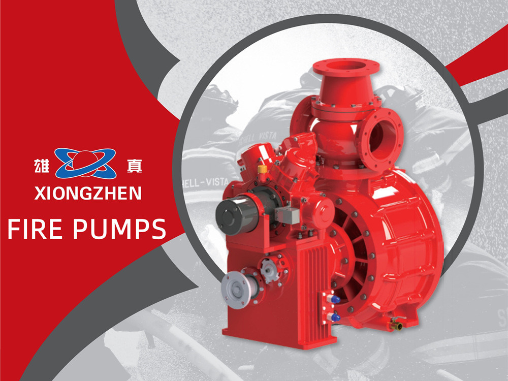
Geleneksel itfaiye araçları için su, yangınla mücadele ve kurtarmada temel ortamdır. İtfaiye araçlarındaki komple su tedarik sisteminin temel güç ünitesi olarak, araç üstü yangın pompası aracın yangın söndürme verimliliğini, su tedarik basıncını ve sürekli çalışma stabilitesini doğrudan belirler. Xiongzhen, uzun yıllardır yangın pompalarının Ar-Ge ve üretimiyle uğraşmaktadır. Yerli ve yabancı olgun pompa yapılarını aşınmaya dayanıklı yeni malzemelerle entegre ederek, tam kapsamlı orta-düşük basınçlı ve yüksek-düşük basınçlı araç üstü yangın pompaları geliştirdik.Tüm ürünler ulusal 3C yangın sertifikasyonunu ve tip denetimini geçmiştir. Stabil su çıkışı, hızlı emiş, kompakt yapı ve kolay bakım özellikleriyle çeşitli su tanklı, köpüklü ve acil kurtarma itfaiye araçlarının dönüşümü ve desteklenmesi için uygundurlar. Xiongzhen yangın pompalarıtam model yelpazesini kapsar: CB10/20, CB10/30, CB10/40, CB10/60, CB10/80, CB10/100, CB10/120 ve CB10/140 dahil düşük basınçlı pompalar; CB20·10/15·30, CB20·10/20·40, CB20·10/30·60 ve CB20·10/40·80 gibi orta-düşük basınçlı pompalar; yüksek-düşük basınçlı pompa CB40·10/7·50 ve ayrıca CB20/15, CB20/20 ve CB20/30 orta basınçlı pompalar. Her model eksiksiz performans özellikleri, isteğe bağlı dişli oranları ve montaj boyutlarıyla tedarik edilir. Hem yurt içinde hem de yurt dışında itfaiye aracı dönüşümü ve acil kurtarma için su tedarik gereksinimlerini karşılayabilen bu pompalar, stabil performans, basit kullanım ve zahmetsiz bakım özelliklerine sahiptir. Xiongzhen serisi yangın pompaları esas olarak pompa gövdesi, yağ doldurma ağzı, su giriş borusu, çek valf, çift pistonlu emiş cihazı, hız ölçüm dişlisi, dişli kutusu ve giriş milinden oluşur. Orta-düşük basınçlı modeller ayrıca orta-düşük basınç geçişi için pnömatik küresel valfler, orta basınç çek valfleri ve düşük basınç çek valfleriyle donatılmıştır. Ünite, dengeli su çıkışı sağlamak için tek parça döküm alüminyum pompa gövdesi kullanır. Çift pistonlu emiş mekanizmasıyla donatılan orta-düşük basınçlı pompalar, elektrik tahriki ve kayış kasnağı tahriki olmak üzere iki tahrik modu seçeneği sunar; hızlı emiş ve kullanıcı dostu çalışma sağlar. Ana Yangın Pompası Modellerinin Parametre Karşılaştırması Farklı çalışma koşullarıyla CB10/40 CB10/60 CB10/100 CB10/140 CB20·10/30·60 CB40·10/7.50 CB20/30 Debi(L/s) 40 60 100 140 60 30 30 28 42 70 98 30 21 60 20 30 50 70 30 15 452 --- 35 (Birleşik düşük basınç) 15 30 --- 15 (Birleşik orta basınç) --- --- Çıkış Basıncı (MPa) 1.0 1.0 1.0 2.0 1.3 2.0 1.3 1.0 1.0 1.0 1.0 1.3 --- 1.0 (Birleşik düşük basınç) 2.0 1.0 --- 2.0 (Birleşik orta basınç) --- --- Nominal Hız (dev/dak) 3135±50 3280±50 2270±50 2600±50 3251±50 2360±50 3145±50 3390±50 3520±50 2320±50 2810±50 3271±50 2502±50 2641±50 3010±50 3120±50 2050±50 2600±50 3090±50 2243±50 2645±50 --- 3202±50(Birleşik) 2850±50 2337±50 Mil Gücü (kW) 60 102 149 212 113 49 122 61 106 138 219 137 49 98 39 73 115 150 80 32 87 135(Birleşik) 68 55 Yangın kurtarma çal...
Detaylar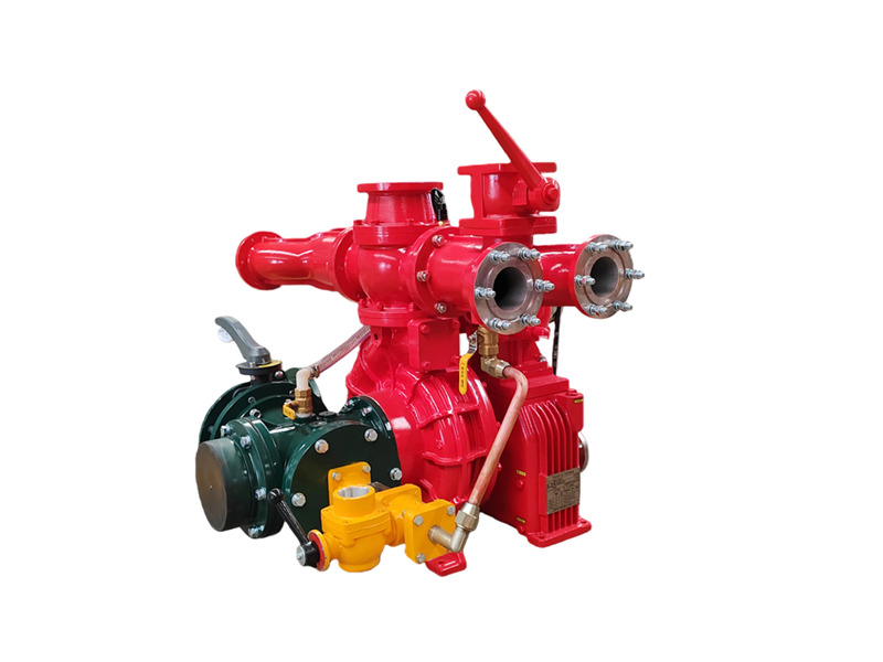
The CB10/60-RS kamyona monte yangın pompası tek kademeli düşük basınçlı santrifüj pompa, çift pistonlu vakum pompası, elektromanyetik kavrama otomatik ayırma cihazı, hız artırıcı, çıkış boru hattı ve kapatma vanası ile giriş boru hattından oluşur. ♦ Ana Yapı ve İşlev (1) Tek kademeli düşük basınçlı santrifüj pompa: Pompa kapağı, pompa gövdesi, birinci kademe çark ve pompa milinden oluşur; nominal basınç ve nominal debiyi sağlar. (2) Hız artırıcı: CB10/60-RS araç üstü yangın pompasının hız artırıcısının geleneksel hız artırma oranı 1.440'tır. (3) Çift pistonlu vakum pompası: Esas olarak piston, pompa gövdesi, pompa mili ve eksantrik çarktan oluşur. Eksantrik çark, piston kılavuz çubuğu ve pompa gövdesi çelik burcu ile donatılmıştır. Piston pompasının her iki ucuna giriş ve çıkış valfleri monte edilmiştir. Elektromanyetik kavrama devreye girdiğinde piston pompası çalışmaya başlar. Çalışma sırasında eksantrik çarkın eksantrik hareketi pistonun ileri geri hareket etmesine neden olur ve böylece pompa ile boru hattındaki havayı kademeli olarak dışarı atarak hava kalitesini iyileştirir. Boşluk içinde vakum oluşturularak su alma amacı gerçekleştirilir. 1. Çıkış kapatma vanası (4 adet); 2. Sol ve sağ çıkış su boruları; 3. Şanzıman soğutma dönüş suyu bağlantısı; 4. Basınç göstergesi bağlantısı; 5. Çıkış çek valfi; 6. Su topu flanşı; 7. Su basıncı anahtarı; 8. PTO soğutma basıncı dönüş suyu bağlantısı; 9. Arka su tankı flanşı; 10. Arka su tankı küresel vanası; 11. Şanzıman; 12. Elektromanyetik kavrama ve kablolama; 13. Pistonlu su alma pompası; 14. Vakum göstergesi bağlantısı; 15. Vakum su alma bağlantısı; 16. Giriş borusu arayüzü; 17. Giriş dört yollu borusu; 18. Su pompası tahliye vanası; 19. Şanzıman soğutma basıncı dönüş suyu borusu; 20. Şanzıman soğutma basıncı giriş suyu borusu; 21. Şanzıman yağlama yağı seviye vanası; 22. Kaplin flanşı; 23. Tahrik kayışı; 24. Köpük oranlayıcı basınçlı su dişli bağlantısı (su tankerlerinde mevcut değildir); 25. Köpük oranlayıcı arayüzü; 26. PTO soğutma basıncı çıkış suyu bağlantısı; 27. CB10/60 araç yangın pompası; 28. Şanzıman soğutma basıncı çıkış suyu bağlantısı; 29. Arka giriş kelebek vanası (4) Düşük basınçlı su çıkış boru hattı ve kapatma vanası:Düşük basınçlı su çıkış çek valfi, sol ve sağ su çıkış boruları, dört su çıkış borusu ve dört su çıkış kapatma vanasından oluşur. (5) Arkaya monte edilmiş su giriş boru hattı:Dört yollu giriş borusu, giriş filtre süzgeci, harici giriş bağlantısı ve dört yollu giriş borusunun her iki tarafındaki bağlantılardan oluşur; sağ tarafta köpük oranlayıcı montajı için bir arayüz bulunur, sol tarafta ise döndürülebilir arka giriş dirseği, 150 mm kelebek vana ve kaynaklanabilir flanş bulunur. ♦Teknik özellikler Model Giriş çapı (mm) Çıkış çapı (mm) Maksimum vakum (kPa) 1 dakika içindeki vakum düşüşü (MPa) 7 m emiş derinliği süresi (s) CB10/60-RS Φ150 Φ80X4 ≥85 ≤2.6 ≤50 Model Çalışma koşulları Emiş derinliği (m) Debi (L/s) Basınç (MPa) Mil hızı (r/dak) Mil gücü (kW) Mak...
Detaylar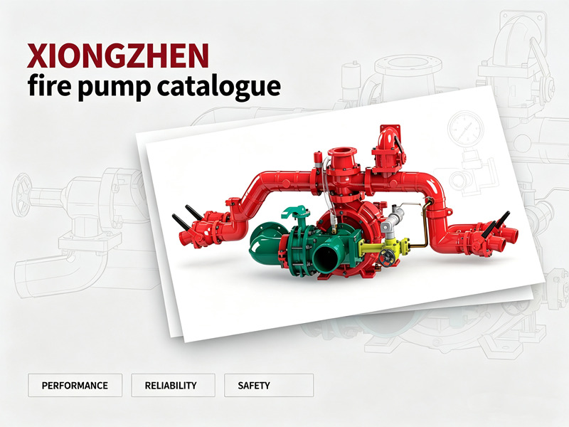
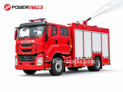
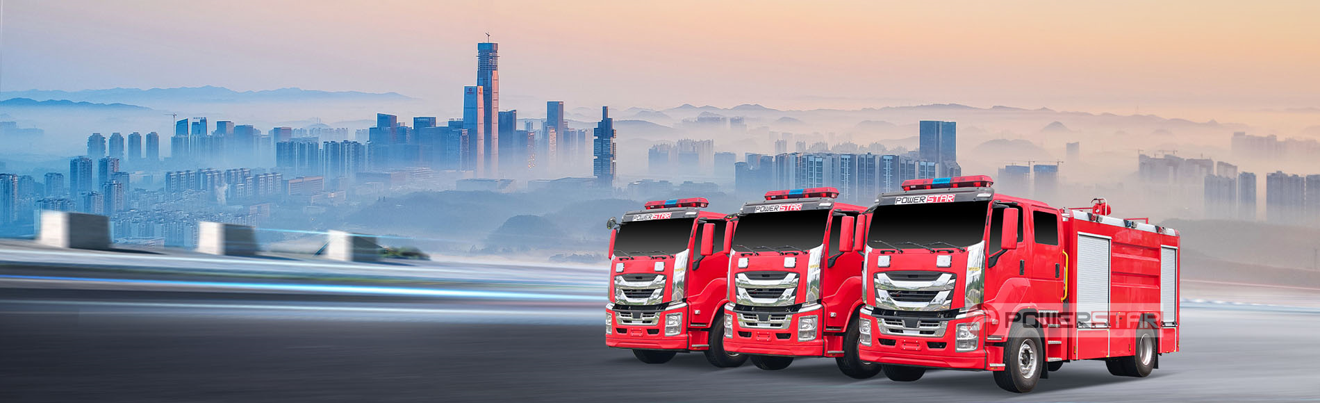
POWERSTAR, profesyonel bir itfaiye aracı üreticisi ve ihracatçısıdır. Ürün yelpazemiz su tanklı itfaiye araçları, köpüklü itfaiye araçları, kuru tozlu itfaiye araçları ve merdivenli itfaiye araçlarını içerir; bu araçlar şehir içi yangın söndürme, petrokimya tesisleri, havaalanları ve deniz limanları, orman yangını koruması ve daha birçok alanda yaygın olarak kullanılmaktadır. ISUZU, HOWO ve FAW şasileri üzerine kurulu itfaiye aracı modellerimiz Güneydoğu Asya, Orta Doğu, Güney Amerika ve Afrika'daki birçok ülke ve bölgeye ihraç edilmektedir. Filipinler hükümetinin toplu satın alımlarından Nijeryalı müşterilerin tekrarlayan siparişlerine kadar POWERSTAR, güvenilir kalitesi ve profesyonel özelleştirme hizmetleri sayesinde küresel müşteriler arasında güçlü bir itibar kazanmıştır. POWERSTAR neden XIONGZHEN yangın pompalarını tercih ediyor?Yangın pompası genellikle bir itfaiye aracının "kalbi" olarak adlandırılır—yüksek verimli ve güvenilir bir yangın pompası olmadan bir itfaiye aracı yalnızca ekipman ve personel taşıyan bir araçtan ibarettir ve gerçek anlamda yangınla mücadele görevlerini yerine getiremez. Bu nedenle POWERSTAR, temel bileşenleri seçerken en yüksek standartlara bağlı kalır.XIONGZHEN, Çin yangın pompası sektöründe tanınmış bir markadır ve ürünleri ülke genelindeki birçok profesyonel itfaiye aracı üreticisi tarafından yaygın olarak kullanılmaktadır. Almanya, Avusturya, Amerika Birleşik Devletleri ve diğer ülkelerin gelişmiş teknolojileri temel alınarak, bağımsız Ar-Ge yetenekleriyle birleştirilen XIONGZHEN, performansı ithal ürünlerle rekabet edebilen araç üstü yangın pompası serileri sunmaktadır. Temel avantajları şunlardır:• Mükemmel performans ve yüksek verimlilik: İki kademeli santrifüj çarkı ve yönlendirici kanatlı pompa gövdesi tasarımı, pompa milindeki radyal ve eksenel kuvvetleri dengeler ve düzgün, verimli çalışmayı sağlar.• Kompakt yapı ve kolay kullanım: Yönlendirici kanat haznesi ile basınç haznesinin entegre tasarımı, bakım ve servis işlemlerini kolaylaştırır.• Yenilikçi emiş teknolojisi: Elektromanyetik kavramalı dört pistonlu elektrikli emiş pompası, geleneksel iki pistonlu pompalara kıyasla daha yüksek su alma kapasitesi ve üstün emiş performansı sağlar; susuz çalışma koşullarında mekanik salmastralarda oluşabilecek kuru çalışma hasarını etkili şekilde önler.• Yetkili sertifikasyon: Tüm ürün serisi, Ulusal Yangın Ekipmanı Kalite Denetim ve Muayene Merkezi tarafından tip testinden geçirilmiş ve GB6245-2006 standardına uygundur. POWERSTAR, güvenilir kaliteleri ve kanıtlanmış teknolojileri nedeniyle XIONGZHEN yangın pompalarını tercih eder; böylece fabrikamızdan çıkan her itfaiye aracının dünya genelindeki yangın söndürme ve kurtarma görevlerinde tutarlı ve güvenilir performans göstermesi sağlanır.XIONGZHEN Yangın Pompası Tam Seri – Teknik Özellikler ve Seçim KılavuzuXIONGZHEN yangın pompaları, farklı tonajlardaki ve uygulamalardaki itfaiye araçlarına uygun, kapsamlı bir düşük basınçlı ve orta-düşük basınçlı ürün yelpaz...
Detaylar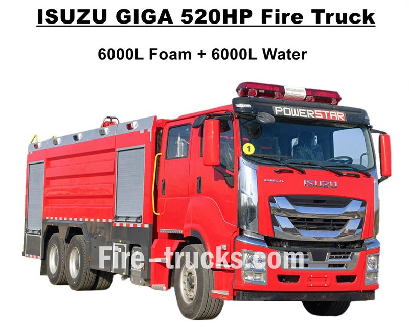
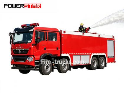
En yüksek kaliteBatı Afrika Burkina Faso'ya ihraç edilen ISUZU GIGA itfaiye araçlarıISUZU GIGA VC66 ağır hizmet tipi 6x4 kamyon şasisi temel alınarak tasarlanan bu araçlar, GIGA VC66 yeni kabin, standart hava süspansiyonlu koltuk ve konforlu sürüş için klima sistemi kullanır. Araç, Japon ISUZU teknolojisine sahip 6WG1-TCG62 model dizel motorla donatılmıştır; 520 HP gücünde olup motor hacmi 15681cc olabilir. FAST 12 vitesli manuel şanzıman ile uyumlu çalışır, çok düşük yakıt tüketimine sahiptir. Standart olarak ön lastikler 385/80R22.5 ve arka lastikler 315/80R22.5 olup toplam 10+1 adettir. Üst gövde ekipmanları arasında 6000L su tankeri ve 6000L köpük tankeri bulunur; tamamı paslanmaz çelik #304 malzemeden yapılmıştır ve uzun süreli kullanım için dayanıklıdır. Tanker üst gövdesinin üzerinde çift yangın monitörü bulunan, 140L/s etkili debiye sahip özelleştirilmiş süper güçlü CB10/140 yangın pompası ile uyumlu çalışır; model PL8/64 ve etkili debisi 64L/s'dir.ISUZU GIGA 520HP itfaiye aracıtüm gerekli yangın söndürme ekipmanlarıyla donatılmıştır; yangın söndürme ve insan kurtarma operasyonları için ideal bir itfaiye aracıdır ve Burkina Faso pazarında yaygın olarak kullanılmaktadır. ISUZU GIGA 520HP 14.000L Köpük Tanklı İtfaiye Aracı CS TRUCKS fabrikası kamyon alanında profesyonel üreticidir,tüm ürünlerin yepyeni ve yüksek kaliteli olmasını garanti eder. ISUZU İtfaiye Aracı Özellikleri: Ad ISUZU GIGA 12000L köpük pompalı itfaiye aracı Kabin GIGA VC66 Motor 520HP ve 15681cc motor hacmine sahip 6WG1-TCG62 Şanzıman FAST 12 vitesli Dingil mesafesi 4600+1370mm Lastik Ön: 385/80R22.5 (2 adet) Arka: 315/80R22.5 (8 adet) Tanker 6000L köpük tankeri (Paslanmaz Çelik #304) 6000L su tankeri (Paslanmaz Çelik #304) Yangın Pompası 140L/s debiye sahip CB10/140 Yangın Monitörü Ön: 64L/s debiye sahip PL8/64 Arka: 64L/s debiye sahip PL8/64 Ekipman Özelleştirilmiş tam set yangın söndürme ekipmanları ISUZU Köpük Tanklı İtfaiye Aracı Nasıl Kullanılır: .
Detaylar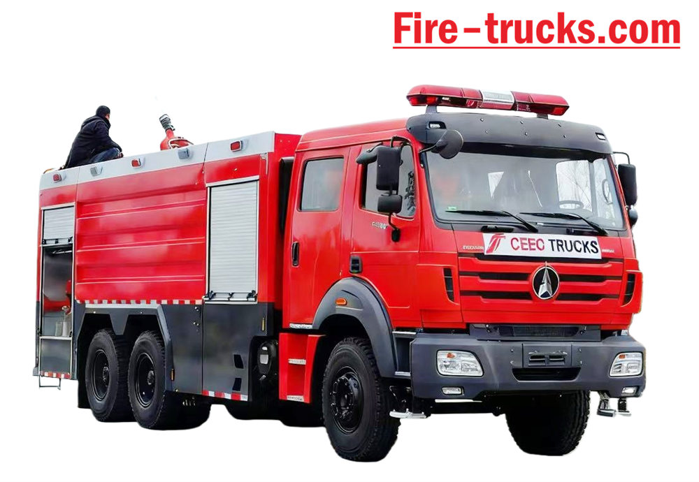
Beiben Beiben 2638 tip II model 6*4 sol direksiyonlu şasi ve gövdeye sahip itfaiye aracı. Kapasite, 10.000 litrelik su tankeri ve 2.000 litrelik köpük tankı dahil olmak üzere 12.000 litreye kadar çıkabilir. Beiben 2638 itfaiye kurtarma kamyon XIONGZHEN CB10/60 yangın pompası ve PL8/48 yangın monitörü ile donatılmış olup, kullanımı son derece kolaydır. Günlük kullanım. Özellikle ihtiyaç duyulan her alanda yangın söndürme projelerinde kullanılır. Bu araç, Beiben marka kamyon şasisinin orijinal avantajlarından tam olarak yararlanacak şekilde tasarlanmıştır. Ürünün kullanışlılığı ve güvenilirliğinin yanı sıra yeni tasarlanmış şasiyi de tam olarak göz önünde bulunduruyoruz. Gövde Malzeme, korozyon önleyici boya ile kaplanmış uluslararası standartlarda karbon çelik ve paslanmaz çeliktir. Paslanmayı önlemek ve uzun ömürlü kullanım sağlamak için etkilidir. Sandviç tipi PTO, yangın pompası, yangın monitörü, mürettebat odası ve hortum ile donatılmış Beiben 6x4 İtfaiye Aracı kutu, pompa odası, kuru toz tankeri ve azot sistemi, boru hattı hortum makarasıyla eşleştirilmiş, İngilizce Versiyon kontrol kutusu, giriş ve çıkış boru hattı, arka tırmanma merdiveni, üst yastık lambası ve gerekli tüm parçalar. Yangın söndürme ekipmanı. Özel tasarımlı, 2+4 koltuklu çift sıralı kabin, keyifli sürüş hissi sunuyor. Bu nedenle, o Bu araç, özellikle yangın söndürme projeleri için ideal bir itfaiye aracıdır. [if gte mso 9]> Normal 0 7.8 磅 0 2 false false false EN-US ZH-CN X-NONE
Detaylar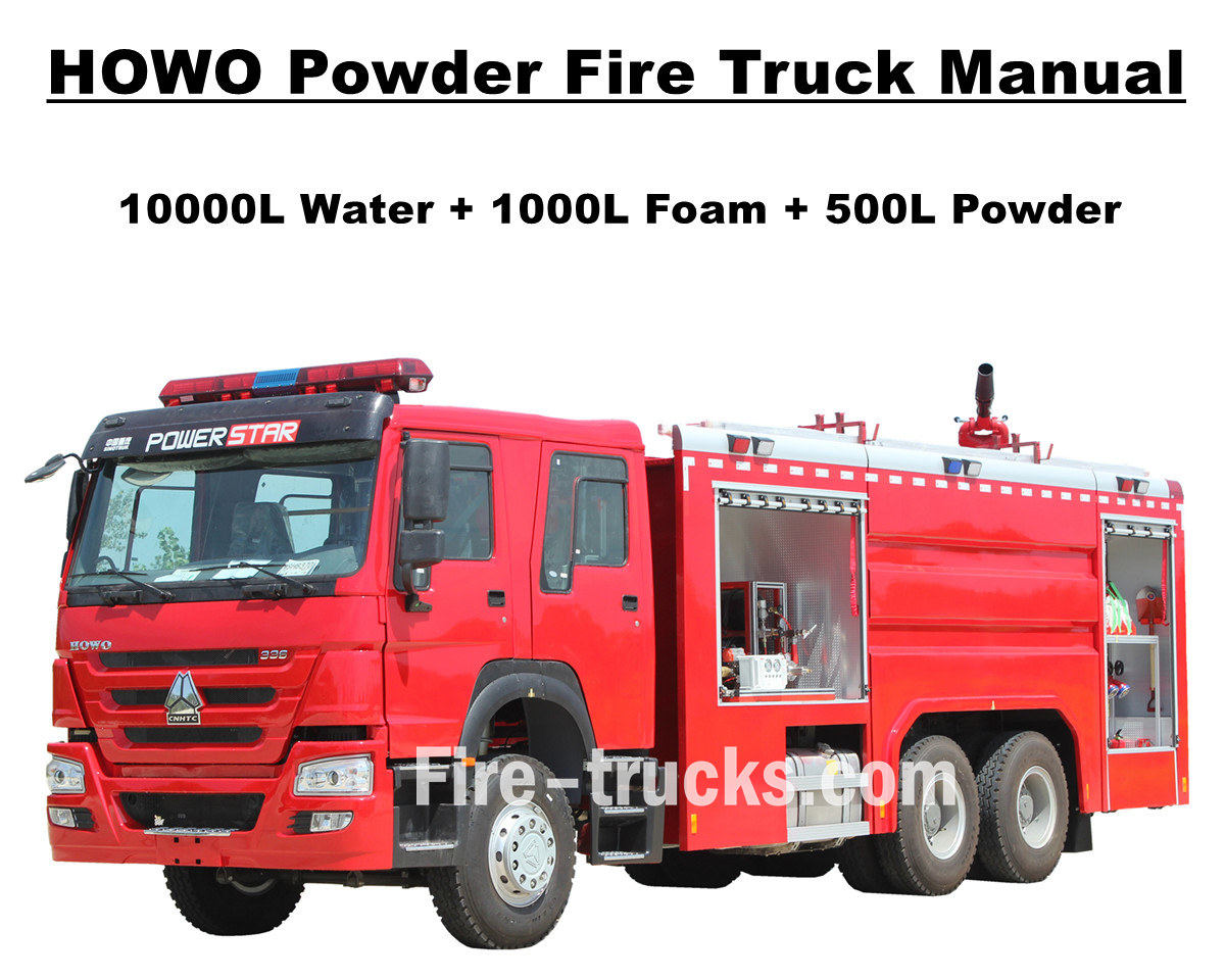
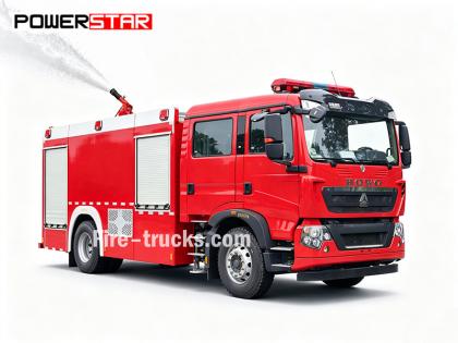
Afrika ve Moritanya'daki müşteri toplam 4 adet ürün satın aldı. Sinotruk HOWO pompalı itfaiye aracı POWERSTAR TRUCKS tarafından üretilen ve başkent Nouakchott'ta kullanılan itfaiye aracı, yangın söndürme aracı veya yangın pompası olarak da adlandırılır ve uluslararası alanda çok sayıda yangın söndürme ve insan kurtarma projesinin ihtiyaçlarını karşılamak üzere tasarlanmış ve üretilmiştir. İtfaiyecilerin taşınması için özel olarak tasarlanmış çift kabin sırası, yangın söndürme, yangın kurtarma vb. için çeşitli yangın söndürme ekipmanları ve aletleri içerir. HOWO itfaiye araçlarının daha verimli çalışmasını garanti etmek için, alüminyum alaşımlı merdivenler, su köpüğü ve kuru toz yangın söndürme maddesi ve depolama tankları, 70 metreden fazla püskürtme mesafesine sahip PL8/48 yangın monitörü ile eşleştirilmiş verimli CB10/60 model yangın pompası, uzun mesafeli yangın söndürme için tabancalı yangın söndürme hortumu makarası, maskeli solunum cihazı, koruyucu giysi, kurtarma aletleri, ilk yardım çantası vb. ile donatılmış özel araçlar sunuyoruz. HOWO itfaiye araçlarının verimli ve güvenilir çalışması için tüm hizmetler sağlanmaktadır. Moritanya'daki müşterilerin HOWO itfaiye araçlarını daha kolay ve verimli bir şekilde kullanmalarını garanti etmek için, tüm araçlar, kullanım kılavuzu, araç kullanım kılavuzu ve yedek parça kılavuzu da dahil olmak üzere, İngilizce versiyonlu eksiksiz bir servis kataloğu ile birlikte verilmektedir. SINOTRUK HOWO 14.000L Toz Pompalı İtfaiye Aracı POWERSTAR fabrikası Kamyon alanında profesyonel bir üreticidir. Tüm ürünlerin yepyeni ve yüksek kaliteli olduğunu garanti ediyoruz. » Ⅰ. HOWO İtfaiye Aracının Avantajları: ★ 247KW / 336HP gücündeki WEICHAI dizel motoru, 100.000 km sorunsuz çalıştı. ★ SINOTRUK HOWO klasik HW76 kabin, Avrupa tasarımı ★ Monte edilmiş CB10/60 yangın pompası, 60 L/s akış hızı, son derece güvenilir. ★ Üstten monte edilmiş PL8/48 su püskürtme topu, dayanıklı kullanım ★ 500 litre kuru toz, azot tüpü ve hava kontrol vanalarıyla birlikte. ★ Köpük ve pudra için entegre kontrol sistemi, arka panel ile birlikte. » II . Howo Kurtarma İtfaiye Aracı Çizimi: [if gte mso 9]> Normal 0 7.8 磅 0 2 false false false EN-US ZH-CN AR-SA /* Style Definitions */ table.MsoNormalTable {mso-style-name:普通表格; mso-tstyle-rowband-size:0; mso-tstyle-colband-size:0; mso-style-noshow:yes; mso-style-priority:99; mso-style-parent:""; mso-padding-alt:0cm 5.4pt 0cm 5.4pt; mso-para-margin:0cm; mso-pagination:widow-orphan; font-size:10.0pt; font-family:"Calibri",sans-serif; mso-bidi-font-family:"Times New Roman";} To guarantee Mauritania Nouakchott clients purchased satisfy HOWO 6x4 Water & Foam & Powder Fire Truck, so we POWERSTAR Engineer Department do design the truck firstly, then start for production. Howo fire truck equipped with Sandwich PTO, fire pump, fire monitor, crew room, hose box, pump room, English version control box, inlet and outlet pipeline, rear climbing ladder, top pillow lamp, all necessary firefighting equipment, and...
Detaylar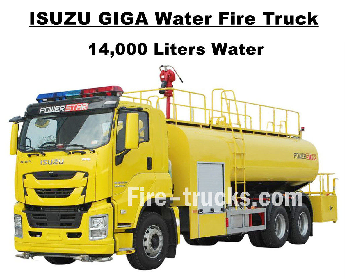
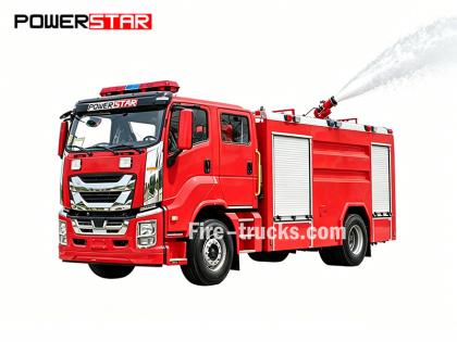
Hondura'dan Güney Amerikalı müşterimiz Bay Joseph, 1 ünite satın aldı Isuzu GIGA VC66 14000L 3700galon su itfaiye aracı POWERSTAR TRUCKS'tan, Japon ISUZU GIGA 6x4 ağır hizmet tipi kamyon şasesi temel alınarak tasarlanan, 280 kW / 380 HP beygir gücüne sahip 6UZ1-TCG60 model dizel motorla donatılmış, 6 silindirli, 4 zamanlı, su soğutmalı, turboşarjlı ve ara soğutmalı bir motor olan, 9839 ml'lik verimli bir deplasmana sahip, uluslararası standart FAST 12 vitesli manuel şanzıman şanzımanıyla uyumlu çalışan, 12 vites ileri ve 2 vites geri vitesli, yakıt tüketimini verimli bir şekilde azaltan, bir stepne dahil olmak üzere 12R22.5 model modeline toplam 13 adet çelik lastik takılmış, çok çeşitli yol koşulları ve dağ tırmanışı için çok uygundur. Dingil mesafesi 4600 + 1370 mm ile birden fazla isteğe bağlı olabilir, birden fazla alana yönelik yangın söndürme projeleri için uygun ve kullanışlı tasarlanmış hizmet. Isuzu GIGA 3700 galonluk su tankeri itfaiye aracı, Japon teknolojisi ISUZU kamyon şasisi, orijinal GIGA VC66 kabinli ve konforlu sürüş için ısıtma ve soğutma fonksiyonlu klima ile donatılmıştır. Ayrıca, 14.000 litrelik (3700 galona eşdeğer) verimli hacme sahip, tamamen paslanmaz çelik SS304 malzemeden su tankeri gövdesi, tanker gövdesinin üst kısmında bir adet Çin malı CB10/60 yangın pompası ve PS8/50 yangın monitörü, tam set yangın söndürme ve kurtarma ekipmanı ve özel limon sarısı boya ile donatılmıştır. Tüm bunlar, aracı Honduras sokaklarında ve topluluklarında yangın söndürme projeleri için ideal bir araç haline getirir. Ayrıca, kullanım kılavuzu için Kullanıcı Kılavuzu, GIGA kamyon kullanımı için Kamyon Kılavuzu ve bakım için Yedek Parça Kılavuzu da dahil olmak üzere servis için tam set İngilizce katalog ile donatılmıştır. Isuzu GIGA 14.000L Su Pompalı İtfaiye Aracı POWERSTAR fabrikası kamyon alanında profesyonel bir üreticidir, Tüm ürünlerimizin Yepyeni ve Yüksek Kalitede olmasını garanti ediyoruz. » Ⅰ. Isuzu Su İtfaiye Aracının Avantajları: ★ 280KW / 380HP güçlü 6WG1 dizel motor, 100.000 km sorunsuz. ★ ISUZU VC66 yeni GIGA kabin, Avrupa tasarımı ★ Monte edilmiş CB10/60 yangın pompası, 60L/s akış hızı, süper güvenilir ★ Üstten monteli PS8/50 su topu, dayanıklı hizmet ★ Yan tarafta panel bulunan entegre kontrol sistemi ★ Kişiye özel limon sarısı boyama, parlak ve güzel CB10/60 yangın pompası Model : CB10/60 Basınç : 1.0Mpa Maksimum Çalışma Basıncı : 1.232Mpa Akış Hızı : 1,0Mpa'da 60L/s, hız 3286±50r/dak, güç 102kW, emiş derinliği 3m 1,3 MPa'da 42 L/s, hız 3519 ± 50 d/dk, güç 106 kW, emiş derinliği 3 m 1,0Mpa'da 30L/s, hız 3120±50r/dak, güç 73kW, emiş derinliği 7m Hız Oranı : 1:1.44 PS8/50 Yangın Monitörü Model : PS8/50 Basınç : 0,8Mpa Çalışma Aralığı : su ≥ 65 M Dikey Dönüş : -45° ~ +70° Yatay Dönüş : 0° ~ 360° Akış Hızı : 50 L/s » II . Isuzu İtfaiye Aracı Çizimi: ISUZU GIGA VC66 14000L su tankeri itfaiye aracı, Güney Amerika ülkesi Honduras'a tasarlanmış ve ihraç edilmiştir. 3700 galonluk su tankeri, tamamı paslanmaz çelik SS304 malzemeden ür...
Detaylar
Powerstar Trucks, Özel Acil Müdahale Araçları ve İtfaiye Araçları Powerstar Trucks Emergency Response, birkaç yıldır özel itfaiye araçlarının uzmanlığıyla önde gelen tam ürün yelpazesi üreticisi olarak mirasını oluşturmuştur. köpüklü su itfaiye araçları Ve kurtarma itfaiye aracı İtfaiyecilerin güvendiği mirasa dayanan Powerstar kamyonları, her itfaiye teşkilatının kendine özgü ihtiyaçlarını karşılamak için esnek, stratejik ve özel çözümler sunarak ilk müdahale ekiplerini ön planda tutar. 120 adet kurtarma itfaiye aracı teslimat için Uganda Polis Teşkilatına 65 Adet Kurtarma İtfaiye Aracı İhraç Edildi Su İtfaiye Araçları Köpüklü yangın söndürme aracı İtfaiye araçları işlevlerine göre başlıca dört kategoriye ayrılır: itfaiye araçları, merdivenli itfaiye araçları, özel amaçlı itfaiye araçları ve lojistik destek itfaiye araçları. 01, İtfaiye araçları yangınları doğrudan söndürmenin ana gücüdür, bunlar arasında şunlar yer alır: * **Su Tanklı İtfaiye Araçları:** Genel yangınları söndürmeye uygun, kendi su tankı ve pompasıyla donatılmış araçlardır. * **Köpüklü İtfaiye Araçları:** Özellikle yağ gibi yanıcı sıvıların sebep olduğu yangınları söndürmek için tasarlanmıştır. * **Kuru Tozlu İtfaiye Araçları:** Gaz ve elektrik yangınlarını söndürmeye uygundur. * **Karbondioksitli İtfaiye Araçları:** Değerli ekipmanları ve hassas aletleri korumak için kullanılır. * **Köpük-Kuru Toz Kombine Kullanımlı Kamyonlar:** Her iki söndürme maddesini aynı anda kullanabilir, geniş uygulama yelpazesine sahiptir. 02, Merdivenli İtfaiye Araçları Yüksek binalarda kurtarma ve yangınla mücadele amacıyla kullanılırlar ve başlıca şunlardır: * **Merdivenli İtfaiye Araçları:** Teleskopik merdivenle donatılmış olup, yüksek yerlerdeki yangınları söndürme ve insanları kurtarma yeteneğine sahiptir. * **Havadan Püskürtmeli Yangın Söndürme Araçları:** Uzaktan kumandalı bom kullanarak söndürme maddelerini uzun mesafelere püskürtürler. * **Hava Platformlu İtfaiye Araçları:** Kurtarma ve yangınla mücadele için hidrolik kaldırma platformu sağlar. İtfaiye aracı uygulaması 03, Özel itfaiye araçları aşağıdaki gibi belirli görevlerden sorumludur: * **Kurtarma ve Afet Yardım İtfaiye Araçları:** Yıkım araçları ve kaldırma ekipmanlarıyla donatılmış, kaza kurtarmada kullanılan araçlardır. * **İtfaiye Araçlarının Aydınlatılması:** Gece kurtarma operasyonları için yüksek yoğunluklu aydınlatma sağlayın. * **Duman Tahliyeli İtfaiye Araçları:** Yer altı yangınlarında duman tahliyesi amacıyla kullanılır. 04, **Lojistik Destek İtfaiye Araçları:** Öncelikle yangın mahalline lojistik destek sağlarlar, örneğin: * **Su Temini İtfaiye Araçları:** Ön saflardaki itfaiye araçlarına sürekli su temini sağlayın. **Ekipmanlı İtfaiye Araçları:
Detaylar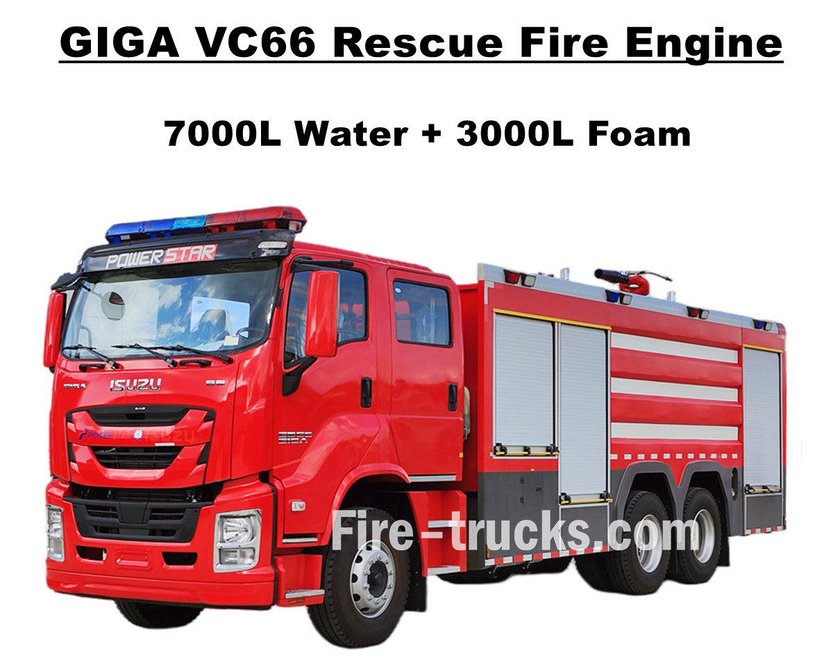
Filipinler Manila müşterileri satın aldı Isuzu GIGA VC66 ağır hizmet tipi itfaiye aracı POWERSTAR TRUCKS'tan, 338kw / 460HP beygir gücüne sahip, 6 silindirli, 4 zamanlı, su soğutmalı, turboşarjlı ve ara soğutmalı Japon ISUZU dizel motoru 6WG1-TCG61 ile donatılmış, 15681cc standart hacimli, uluslararası standart FAST 12 vitesli manuel şanzıman şanzımanıyla uyumlu, 12 vites ileri ve 2 vites geri hareket ediyor, çok düşük yakıt tüketimi, 315 / 80R22.5 modelinde bir stepne dahil olmak üzere toplam 13 adet tubeless lastik takılmış, çok çeşitli yol koşullarına çok uygundur. ve birden fazla bölge için yangın söndürme projesi hizmeti. Orijinal ISUZU GIGA VC66 kamyon şasisine tamamen güveniyoruz, önde 2+1 normal koltuk ve arkada 4 SCBA koltuğu bulunan modifiye edilmiş GIGA çift sıralı kabin, konforlu sürüş için kabinde ısıtma ve soğutma fonksiyonlu klima bulunuyor. Ayrıca, tamamen paslanmaz çelik SS304 malzemeden tanker gövdesi, arka pompa bölmesinde birinci sınıf Çin markası XIONGZHEN CB10/60 yangın pompası, tanker gövdesinin üst kısmında WESTER PL8/48 yangın monitörüyle uyumlu çalışma ve tam set yangın söndürme kurtarma ekipmanıyla donatılmış. Tüm bunlar, kamyonu Manila sokaklarında ve çevresinde yangın söndürme projeleri için ideal bir araç haline getiriyor. Ayrıca, kullanım kılavuzu için Kullanıcı Kılavuzu, GIGA kamyon kullanımı için Kamyon Kılavuzu ve bakım için Yedek Parça Kılavuzu da dahil olmak üzere servis için tam set İngilizce katalogla donatılmış kamyon. Isuzu 7.000L Su 3.000L Köpüklü Yangın Söndürme Aracı POWERSTAR fabrikası kamyon alanında profesyonel bir üreticidir, Tüm ürünlerimizin Yepyeni ve Yüksek Kalitede olmasını garanti ediyoruz. » Ⅰ. Isuzu 6WG1 İtfaiye Aracının Başlıca Özellikleri: ★ 338KW / 460HP güçlü 6WG1 dizel motor, 100.000 km sorunsuz. ★ ISUZU VC66 yeni GIGA kabin, Avrupa tasarımı ★ Arkada 4 SCBA koltuğu bulunan çift sıra kabin ★ Monte edilmiş CB10/60-XZ yangın pompası, 60L/s akış hızı, son derece güvenilir ★ Üstten monteli PL8/48 köpük ateş topu, dayanıklı hizmet ★ Arka panelde entegre kontrol sistemi CB10/60-XZ yangın pompası Model : CB10/60-XZ Basınç : 1.0Mpa Maksimum Çalışma Basıncı : 1.232Mpa Akış Hızı : 1,0Mpa'da 60L/s, hız 3286±50r/dak, güç 102kW, emiş derinliği 3m 1,3 MPa'da 42 L/s, hız 3519 ± 50 d/dk, güç 106 kW, emiş derinliği 3 m 1,0Mpa'da 30L/s, hız 3120±50r/dak, güç 73kW, emiş derinliği 7m Hız Oranı : 1:1.44 PL8/48 Yangın Monitörü Model : PL8/48 Basınç : 0,8Mpa Çalışma Aralığı : Köpük ≥ 70m ve Su ≥ 60m Dikey Dönüş : -45° ~ +70° Yatay Dönüş : 0° ~ 360° Akış Hızı : 48 L/s » II . Isuzu İtfaiye Aracı teknik çizimi: ISUZU GIGA VC66 itfaiye aracı, su ve köpük tankeri ile donatılmış olup, XIONGZHEN CB10/60 yangın monitörü ve Wester PL8/48 yangın monitörü ile eşleştirilerek Filipinler Manila için ideal bir itfaiye kurtarma aracı hizmeti sunmaktadır. » Ⅲ . GIGA itfaiye aracına genel bakış: ISUZU GIGA VC66 yeni model ağır hizmet tipi itfaiye araçları, yangın söndürme ve insan kurtarma için ideal bir itfaiye kurtarma aracıdı...
Detaylar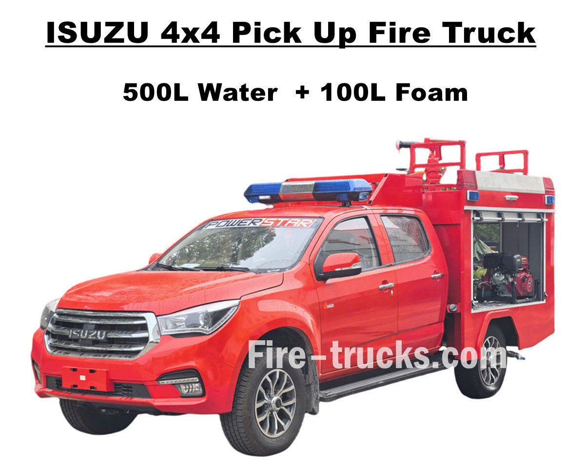
Fabrika satışı ISUZU 4x4 offroad kamyonet itfaiye aracı ISUZU TAGA dört tekerlekten çekişli şasiyi kullanır ve her türlü zorlu yola meydan okumak için mükemmel bir güç sistemi entegre eder. Isuzu pikap itfaiye aracı, 500 litre su deposu ve 100 litre köpük deposu dahil olmak üzere tamamen paslanmaz çelik SS304 malzeme tankeri tertibatı ve arka pompa odasına monte edilecek profesyonel bir bağımsız yangın pompası JBQ4.5/9 ile donatılmıştır. Uzun püskürtme mesafesi ve isteğe bağlı kontrol paneli dili mevcuttur. Ayrıca, farklı ihtiyaçları karşılamak için çeşitli opsiyonel konfigürasyonlar sunar ve su jeti için PS20 yangın monitörü ile üst tarafa monte edilmiştir. Bu ISUZU Pickup 143HP yangın pompası aracı, yangın güvenliği için sağlam bir garanti sağlar ve mükemmel performans ve esneklik gösterir. Isuzu itfaiye aracının orijinal çift sıralı kabini, yangın söndürme ekipmanlarını yüklemek ve iyi bir sürüş performansı sağlamak için yeterli alan ve kalite sağlar. Kabin 5 itfaiyeciyi barındırabilir ve sürücünün her türlü hava koşulunda rahat kalmasını sağlamak için klima ile donatılmıştır. Tüm bunlar, ISUZU 600L köpük itfaiye aracının Arnavutluk pazarı için ideal bir yangın kurtarma aracı hizmeti olmasını garanti eder. Ve aşağıda yer alan Kullanım Kılavuzu güvenli kullanım ve çalışma için donatılmıştır. » Ⅰ. Isuzu Pick Up İtfaiye Aracının Başlıca Özellikleri: ★ 105KW / 143HP güçlü 4KH1 motor, 100.000 km sorunsuz. ★ ISUZU TAGA yeni pikap kabini, Avrupa tasarımı ★ 5 itfaiyeciye uygun orijinal çift kabin ★ Bağımsız JBQ4.5/9 yangın pompası, son derece güvenilir ★ Üstten monteli PS8/20 ateş topu, dayanıklı hizmet » Ⅱ. İtfaiye aracı genel bakışını alın: ISUZU 4x4 Offroad AWD Su Köpüklü İtfaiye Aracı, topluluk, orman, fabrika vb. dahil olmak üzere birçok alanda hizmet veren, her türlü arazide kullanılabilen bir itfaiye kurtarma aracıdır. Arazi kabiliyeti ve dar görünümü sayesinde bu Isuzu Pickup itfaiye aracı, birden fazla görevi başarıyla tamamlayabilir. İtfaiye araçlarımızı daha uygun hale getirmek için, aşağıda farklı müşteriler için seçenekler bulunmaktadır. ----- Tanker malzemesi : Karbon çeliği, paslanmaz çelik, alüminyum alaşımı, PP malzeme ----- Yangın Pompası : Tanker gövdesine ve püskürtme mesafesine bağlı olarak, isteğe bağlı Amerikan Darley marka ----- İsteğe bağlı: Boru hattı, hortum makarası, alüminyum merdiven, Bağlantı modeli (Çin, Avrupa, Amerikan tipi) » Ⅲ. Çekici Görünüm: ISUZU 4x4 AWD pikap itfaiye aracı güçlü ve hızlı tepki verir, yangın yerine hızla ulaşabilir ve zorlu arazilerden kolayca geçebilir. Üstteki yangın topu uzun menzilli ve yüksek akış hızına sahiptir ve tabancalı 50 metrelik uzun yangın söndürme hortumu makarası, yangın kaynağını isabetli bir şekilde vurarak etkili bir şekilde örter ve izole eder. Pikap tipi yangın pompalı araçlar, eksiksiz kurtarma ekipmanlarıyla donatılmıştır. Binalar, ormanlar, petrol tankları ve tehlikeli kimyasal sızıntılar gibi farklı yangın alanları için, hızlı çatışmalar veya hassas müdahaleler için kull...
Detaylar
Lütfen okumaya devam edin, haberdar kalın, abone olun ve düşüncelerinizi bizimle paylaşmanızı bekliyoruz.

 IPv6 Ağ Desteklendi

 Türkçe
 English
 français
 Deutsch
 русский
 italiano
 español
 português
 Nederlands
 العربية
 日本語
日本語 한국의
한국의 Melayu
 ไทย
ไทย Tiếng Việt
 Indonesia
  中文
中文 қазақ
қазақ Filipino
 မြန်မာ
 српски