Mesaj Bırakın
Ürünlerimizle ilgileniyorsanız ve daha fazla bilgi edinmek istiyorsanız, lütfen buraya bir mesaj bırakın, en kısa sürede size cevap vereceğiz.

The fire truck PTO (Power Take-Off) is a power transmission device that transfers engine power to the fire pump. When the firefighter activates the PTO, mechanical power from the engine is transmitted through the transmission and PTO to the fire pump — this is the core working principle of how a fire fighting truck PTO system operates — enabling the pump to deliver high-pressure, high-flow water or foam without the need for a separate auxiliary engine.
Modern fire trucks typically use side-mounted PTO or full power PTO systems. These offer stable power output, convenient operation, and low maintenance costs, making them an essential component of the fire truck's firefighting system.
 Work")
PTO (Power Take-Off) is a critical component in the fire truck's power system. It is a gear transmission device installed between the engine and the transmission, designed to "divert" a portion of mechanical power from the vehicle's engine or transmission to the fire pump or other auxiliary equipment, without affecting the vehicle's normal driving capability.
The fire truck engine is originally responsible only for driving the wheels. However, once the fire truck arrives at the fire scene, the wheels no longer need power, while the fire pump requires power to draw and pressurize water. The PTO is the device that accomplishes this "power switch."

Power Take-Off (PTO) literally means "power output device."
On a fire truck, it refers to extracting rotational power from the engine flywheel or transmission gears through gear engagement, and delivering it to the fire pump or other auxiliary equipment.
Its name describes its function:
Engine = Power source
PTO = Power distributor
Fire pump = Power consumption end
Therefore, the PTO is the bridge connecting the "power source" and the "firefighting system."
The core reason fire trucks must be equipped with a PTO is that firefighting operations require continuous, stable, high-power output that cannot rely on the vehicle's driving state.
Main reasons:
1. Provides continuous firefighting power
The fire pump needs to run for extended periods during firefighting operations. The PTO allows the engine to continuously drive the fire pump at idle or fixed RPM, ensuring stable water pressure and flow.
2. Improves power utilization efficiency
Without a PTO, a separate auxiliary engine would be required to drive the fire pump, which would increase:
Cost
Maintenance complexity
Risk of failure
Space occupation
The PTO directly utilizes the vehicle's engine power, improving overall efficiency.
3. Supports multiple firefighting systems
Modern industrial fire trucks may include not only water pumps but also:
Foam systems
Dry powder systems
High-pressure water systems
Remote-controlled fire monitors
Without a PTO, there are only two solutions:
Install a separate engine to drive the pump → increases weight, cost, maintenance points, and occupies space
Keep the pump permanently connected to the transmission → pump stops when vehicle stops, unable to pump water on site
The PTO solves both problems at once:
| Mode | PTO Status | Power Destination | Result |
| Driving mode | Disengaged | All to wheels | Normal driving |
| Firefighting mode | Engaged | All to fire pump | Pumping while stationary |
The PTO is essentially a "power distribution and conversion system" that transforms vehicle driving power into firefighting operational power.
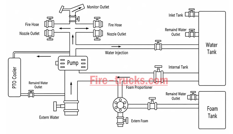
From an engineering perspective, the complete power path is:
Engine → Transmission → PTO → Drive Shaft → Fire Pump → Fire Monitor/Hose System
The PTO's working principle can be summarized in three key stages: power take-off, engagement, and transmission.
The PTO draws power from the engine. Depending on the installation position, the power take-off method differs:
| PTO Type | Installation Position | Power Source | Characteristics |
| Side-mounted PTO | Transmission side | Transmission countershaft gear | Simple structure, lower power (≤50% engine power) |
| Sandwich PTO | Between engine and transmission | Engine flywheel | Full power output, mainstream configuration |
| Split-shaft PTO | Between transmission and driveshaft | Transmission output shaft | High power, allows pumping while driving |
After the driver presses the PTO switch in the cab, the engagement mechanism activates:
| Engagement Method | Working Principle | Common On |
| Electric solenoid control | Electrical signal activates solenoid, pushing shift fork | Mainstream on modern fire trucks |
| Pneumatic control | Compressed air pushes piston, actuating fork | Large fire trucks |
| Manual cable | Mechanical cable directly pulls fork | Older vehicles |
Operation sequence:
Press PTO switch → Solenoid/cylinder actuates → Shift fork pushes sliding gear → Meshes with flywheel or transmission gear → Power connected
After the PTO output shaft begins rotating, power is transmitted through the drive shaft to the fire pump:
PTO output shaft rotates → Drive shaft → Fire pump input shaft → Pump impeller rotates → Water is pressurized and discharged
| Step | Action | Result |
|---|---|---|
| Step 1 | Engine starts, vehicle idling or driving | Engine running, PTO disengaged |
| Step 2 | Arrive at scene, driver presses PTO switch | Driving power disengaged (on some models), PTO gear activated |
| Step 3 | PTO establishes power connection with transmission | Transmission power is diverted to PTO output shaft |
| Step 4 | Drive shaft transmits power to fire pump | Fire pump begins receiving continuous mechanical power |
| Step 5 | Fire pump impeller rotates at high speed | Suction → Pressurization → Delivery to discharge lines → Firefighting |
| Step 6 | System reaches balanced RPM | Stable output, adjustable pressure, flow, and spray pattern |
The fire truck PTO system is a complete power transmission chain, with multiple components working together to transfer engine power to the fire pump. The system can be broken down into six core components:
The engine is the power source of the PTO system and the heart of the entire fire truck.
Function: Generates raw rotational power, driving the flywheel or crankshaft.
Power output: Typically 300–600 HP (depending on chassis model and configuration).
Relationship with PTO: The PTO draws power from the engine flywheel or crankshaft — it is the starting point of power.
Key characteristic: Engine RPM directly affects PTO output speed and the fire pump's water discharge capability. Fire trucks are typically equipped with high-power diesel engines, which not only drive the vehicle but also provide ample power reserve for the fire pump. After PTO engagement, the operator can control pump discharge pressure by adjusting engine RPM.
The transmission is responsible for power delivery and speed matching.
Function: Receives engine power and adjusts speed and torque through different gear combinations.
Relationship with PTO: Side-mounted PTO draws power from internal transmission gears; sandwich PTO is installed at the front of the transmission.
Key characteristic: Transmission gear position does not affect PTO output speed — PTO operates independently of gear selection.
Two power take-off positions:
Transmission side window take-off: PTO mounted on transmission side, drawing power from countershaft or intermediate shaft gears; common on medium-duty fire trucks.
Transmission rear-end take-off (sandwich): PTO installed between engine and transmission, drawing power directly from the flywheel, enabling full power output.
The PTO is the core of the entire system, responsible for "extracting" power from the engine and delivering it to the fire pump.
Function: Extracts power from the engine or transmission and converts it to the speed and torque suitable for the fire pump.
Installation position: Transmission side (side-mounted) or between engine and transmission (sandwich).
Key characteristic: Determines power transmission efficiency, speed matching, and operational convenience.
The drive shaft is the "power bridge" connecting the PTO and the fire pump.
Function: Transmits rotational power from the PTO output shaft to the fire pump input.
Structure: Typically consists of a metal shaft tube, universal joints, and splined connections.
Key characteristic: Must be precisely aligned to avoid vibration; universal joints allow angular compensation.
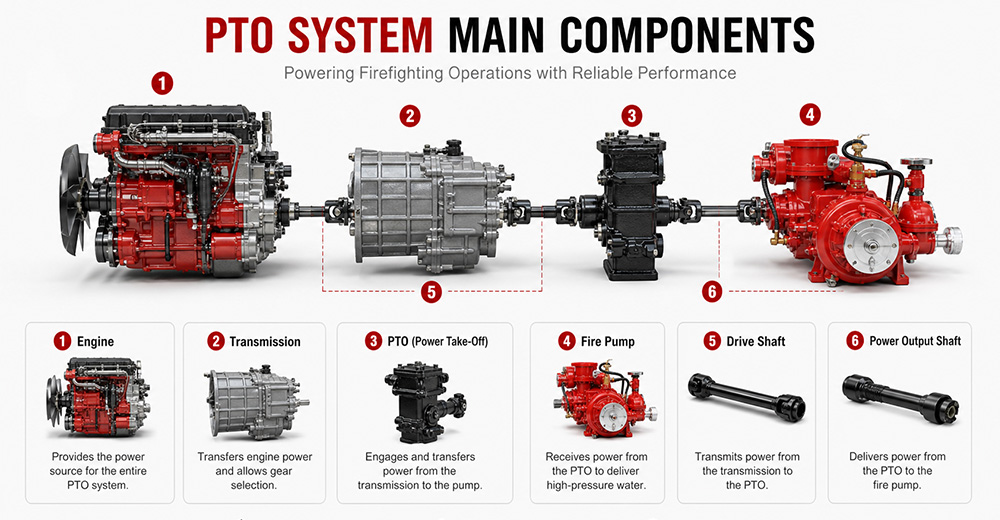
The fire pump is the final load of the PTO system, responsible for converting mechanical energy into water pressure energy.
Function: Receives rotational power from the PTO, drives the impeller to rotate, draws water in, and discharges it under high pressure.
Type: Centrifugal pump (single-stage, two-stage, or multi-stage).
Typical flow rate: 20 L/s – 180 L/s (1,200 – 6,000 L/min).
Typical pressure: 1.0 – 2.5 MPa (10 – 25 bar).
The PTO control system is the "command center" between the driver and the PTO system, responsible for engagement, disengagement, safety protection, and status indication.
Function: Controls PTO engagement and disengagement, monitors system status, and provides safety protection.
Operating location: Cab interior (primary control) and pump panel (auxiliary control).
Control methods: Manual cable, electric solenoid, pneumatic.
Specific control functions:
(1) PTO Engagement Control
The operator presses the PTO switch (electric solenoid/pneumatic) or pulls the lever (manual) in the cab. The control system sends a signal to engage the PTO's internal gears with the power source. After successful engagement is confirmed, an indicator light illuminates, allowing the operator to increase engine RPM.
(2) PTO Disengagement Control
The operator presses the switch again or resets the lever. The control system cuts the signal, and the PTO gears disengage. After disengagement is confirmed, the indicator light turns off.
| PTO Type | Installation Position | Power Source | Power Output | Typical Application |
| Sandwich PTO | Between engine and transmission | Engine flywheel | Full power (≥90%) | Fire pumpers, aerial trucks |
| Split-shaft PTO | Middle of chassis driveshaft | Transmission output shaft | Full power | Large vacuum trucks, airport fire trucks |
| Side-mounted PTO | Transmission side | Transmission gears | Partial power (lower) | Sprinkler trucks, small vacuum trucks |
Sandwich PTO
Advantages: Full power output (≥90%), supports "pumping while driving" (dual-function), high transmission efficiency, easy lubrication.
Disadvantages: Higher cost, complex installation, requires modification to the engine-transmission connection.
Split-shaft PTO
Advantages: Full power output, no additional space required, high reliability, good dynamic balance, can replace auxiliary engine to drive large pumps.
Disadvantages: Requires cutting the original driveshaft, installation position selection must consider driveshaft angle and length compensation.
Side-mounted PTO
Advantages: Low cost, simple installation, can draw power directly from the transmission side.
Disadvantages: Only partial power available, lower output torque, cannot drive high-power fire pumps, mainly used for low-speed, low-power equipment.
 for Fire Trucks")
The process follows a clear mechanical transmission chain:
Engine → PTO → Drive Shaft → Fire Pump → Impeller Rotation → Suction → Pressurization → Fire Monitor
| Factor | Role |
|---|---|
| Centrifugal pump characteristic | When impeller speed is constant, discharge pressure remains naturally stable |
| PTO rigid connection | No slippage or power loss, ensuring continuous stable power input |
| Pressure governor | Automatically detects flow changes and adjusts engine RPM to maintain set pressure |
| Relief valve | Automatically bypasses when pressure exceeds limit, preventing equipment damage |
① Pump speed is determined by engine RPM
Fire pump impeller speed = Engine RPM × PTO ratio. The PTO ratio is fixed (e.g., 1.75:1), so pump speed changes directly with engine RPM.
Calculation formula:
Engine RPM × PTO ratio = Pump speed (RPM)
② Physical relationship between pressure and speed
The pressure generated by a centrifugal pump is proportional to the square of the impeller speed. This physical law means that small changes in RPM cause significant pressure fluctuations.
Speed increases → Centrifugal force increases → Discharge pressure rises
Speed decreases → Centrifugal force decreases → Discharge pressure drops

1. PTO will not engage
Possible causes: Low air pressure (pneumatic type), faulty solenoid, damaged or stuck cable, interlock conditions not met (parking brake not applied, transmission not in neutral).
Solutions: Check air system pressure (must be ≥0.6 MPa); test solenoid; inspect cable; confirm parking brake is applied and transmission is in neutral.
2. PTO engages but pump does not work
Possible causes: PTO clutch failure, broken drive shaft or worn splines, damaged internal gears.
Solutions: Check PTO clutch engagement; inspect drive shaft for breakage or loose connections; disassemble and inspect internal gears.
3. PTO unusual noise
Possible causes: Poor gear meshing or wear, worn bearings, insufficient or degraded lubrication, PTO not fully disengaged.
Solutions: Check gear clearance and tooth wear; inspect bearings; replace with qualified lubricant; confirm PTO is fully disengaged.
4. PTO oil leakage
Possible causes: Worn or deteriorated seals, cracked housing, loose mounting bolts.
Solutions: Replace seals (O-rings, oil seals); inspect housing for cracks; tighten mounting bolts.
5. PTO overheating
Possible causes: Prolonged high-load operation, insufficient or degraded lubricating oil, cooling system failure.
Solutions: Reduce load or shut down for cooling; replace with qualified lubricant; inspect cooling lines.
6. PTO insufficient power
Possible causes: Improper PTO ratio selection, engine RPM set too low, clutch slippage.
Solutions: Confirm PTO ratio matches the fire pump; increase engine RPM to rated operating range; inspect clutch for slippage.
Q1. What does PTO stand for on a fire truck?
PTO stands for Power Take-Off. It is a mechanical system that transfers engine power from the truck's transmission to the fire pump. In simple terms, PTO allows the fire truck's engine to power the pumping system so it can deliver high-pressure water or foam for firefighting operations without needing a separate engine. It is a critical component in industrial and municipal fire trucks.
Q2. Why do fire trucks need a PTO?
Fire trucks need a PTO because it enables the vehicle's main engine to drive the fire pump efficiently. Without a PTO, the fire pump would require a separate engine, which increases cost, weight, and maintenance complexity. PTO systems provide a compact, reliable, and fuel-efficient way to ensure continuous water or foam supply during firefighting operations.
Q3. Can a fire truck operate without a PTO?
Most modern fire trucks cannot operate their pumping system without a PTO because the PTO is responsible for transferring engine power to the fire pump. However, some specialized fire vehicles may use an independent auxiliary engine to drive the pump. These designs are less common due to higher cost, increased maintenance, and lower efficiency compared to PTO-based systems.
Q4. What is the difference between PTO and a fire pump?
The PTO is a power transmission device, while the fire pump is a water or foam pumping system. The PTO delivers mechanical power from the engine to the pump, and the fire pump converts that power into hydraulic pressure to move water or foam. In short, PTO is the "power source connector," and the fire pump is the "firefighting output device."
Q5. How much power can a fire truck PTO provide?
The power output of a fire truck PTO depends on the vehicle design and transmission system. Typically, PTO systems can provide between 50 kW to over 300 kW of mechanical power. Heavy-duty industrial and airport fire trucks often use high-capacity PTO systems capable of supporting large-flow fire pumps and continuous high-pressure operations.
Q6. What are the different types of fire truck PTOs?
There are several types of fire truck PTO systems, including side-mounted PTO, rear-mounted PTO, split shaft PTO, and full power PTO. Side-mounted PTO is commonly used in standard fire trucks, while split shaft and full power PTO systems are used in industrial and airport fire trucks where higher power output and continuous operation are required.
Q7. How do you maintain a fire truck PTO?
PTO maintenance includes regular inspection of lubrication oil levels, checking for leaks, tightening mounting bolts, and ensuring proper alignment of the drive shaft. Operators should also test engagement and disengagement functions regularly. Preventive maintenance is essential to avoid overheating, mechanical wear, and unexpected failure during emergency operations.
Q8. What causes a fire truck PTO to fail?
Common causes of PTO failure include insufficient lubrication, worn gears, misalignment of the drive shaft, overheating, and improper operation by the driver. Electrical or hydraulic control system failures can also prevent PTO engagement. Regular maintenance and correct operating procedures significantly reduce the risk of PTO failure.
Q9. Which PTO is best for industrial fire trucks?
For industrial fire trucks, the best option is usually a split shaft PTO or full power PTO system. These systems can handle high power output, continuous operation, and large-capacity fire pumps. They are widely used in petrochemical plants, refineries, airports, and large industrial facilities where reliable and long-duration firefighting performance is required.
Q10. What should buyers consider when choosing a fire truck PTO?
Buyers should consider engine power compatibility, required fire pump flow rate, vehicle type, and working environment. It is also important to evaluate PTO durability, cooling performance, maintenance accessibility, and compatibility with the chassis. For export projects, compliance with international standards and local regulations should also be taken into account to ensure approval and operational reliability.
PTO (Power Take-Off) is the core system that transfers engine power to the fire pump — it determines whether the entire firefighting system can operate properly.
The fire truck power chain is: Engine → Transmission → PTO → Drive Shaft → Fire Pump → Fire Monitor. Any weak link in this chain affects final firefighting performance.
The primary function of the PTO is to provide stable, continuous mechanical power output, enabling the fire truck to deliver efficient water or foam supply without requiring a separate engine.
Different PTO types (Side-mounted, Rear-mounted, Split shaft, Full power) are suited to different fire truck classes. Industrial fire trucks typically prioritize high-power PTO systems.
PTO performance must match the fire pump flow rate and vehicle chassis, otherwise issues such as insufficient power, unstable pressure, or system overload may occur.
Regular PTO system maintenance (lubrication, tightening, alignment inspection) is key to ensuring reliable fire truck operation, especially in high-intensity industrial applications.
When purchasing industrial fire trucks, buyers should not focus solely on price. PTO power, stability, compatibility, and after-sales support are equally critical factors to evaluate.
For high-risk scenarios such as petrochemical plants, airports, and large industrial parks, Full Power PTO or Split Shaft PTO systems are recommended to ensure continuous operational capability.


Aşağıdaki bilgilerle ilgilenebilirsiniz
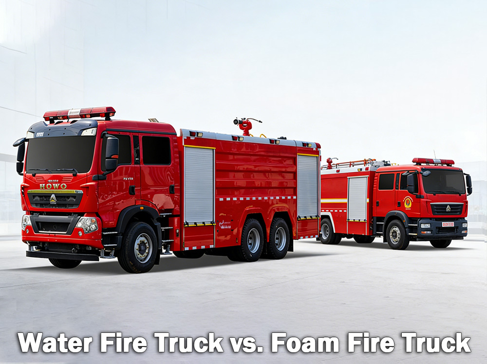
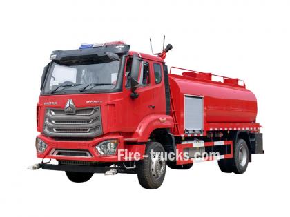
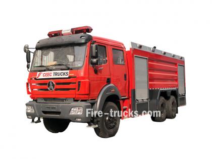
Su ve itfaiye araçları Ahşap, kağıt ve kumaş gibi sıradan yangınlarla mücadele etmek için köpüklü itfaiye araçları kullanılır. Köpüklü itfaiye araçları ise benzin ve yağ gibi yanıcı sıvı yangınlarıyla mücadele eder. Hangisinin doğru olduğu, mevcut tehlikelere bağlıdır. A su itfaiye aracı Büyük bir su deposu taşır ve suyu hortumlar veya su topu aracılığıyla iletmek için yüksek basınçlı bir pompaya güvenir. Dünya çapında belediye itfaiye teşkilatları ve endüstriyel tesisler tarafından kullanılan en yaygın itfaiye aracı türüdür. A köpük itfaiye aracı Öte yandan, özel olarak yangın söndürme köpüğü taşımak ve dağıtmak için tasarlanmıştır. Su tek başına yangını etkili bir şekilde söndüremediğinde -örneğin yanıcı sıvılar, kimyasallar veya yakıt yangınlarında- köpük daha iyi bir seçenektir. Köpük, yangının üzerine bir örtü oluşturarak oksijeni keser ve yeniden tutuşmayı önler. I. Su İtfaiye Aracı Nedir? Su itfaiye aracı, adından da anlaşılacağı gibi, yangınlara su püskürtmek için büyük bir su deposu, güçlü bir pompa ve hortumlar veya monitörlerle donatılmış bir araçtır. Su deposu genellikle 500 ila 3.000 galon (yaklaşık 2.000 ila 12.000 litre) su alır. Pompa, suyu depodan veya yangın musluğu, göl veya gölet gibi harici bir kaynaktan çeker ve ardından yüksek basınç altında hortumlardan geçirir. Su püskürtmeli itfaiye araçlarının en iyi performans gösterdiği yerler: Suyla çalışan itfaiye araçları idealdir... A sınıfı yangınlar Bunlar, sıradan yanıcı maddeleri içerir: Ahşap ve kereste Kağıt ve karton Kumaş ve tekstil Kauçuk ve plastikler Çimen, çalı ve orman malzemeleri Yangın ev, depo veya tarlada yanan malzemeleri kapsıyorsa, su genellikle yangını söndürür. Suyun sınırlamaları: Suyun önemli bir zayıf noktası var. Benzin, yağ veya kimyasallar gibi yanan sıvılara püskürtüldüğünde, su bu yakıtlardan daha ağır olduğu için dibe çöker. Yakıt üstte kalır ve yanmaya devam eder. Bazı durumlarda su, yangını daha geniş bir alana yayabilir. Bu nedenle, su tek başına yanıcı sıvı yangınlarında etkili değildir. Sulu itfaiye aracının yangın pompası özellikleri: Su itfaiye aracı yangın monitörü Özellikler: II. Köpükle Çalışan İtfaiye Aracı Nedir? Köpük itfaiye aracı, yangın söndürme köpüğünü taşımak ve dağıtmak için tasarlanmış özel bir araçtır. Su ve köpük konsantresi için iki ayrı tank taşır. Köpük oranlama sistemi, ikisini belirli bir oranda, genellikle %1, %3 veya %6 köpük konsantresi suya karıştırır. Bu karışım daha sonra hava eklenen bir köpük nozulundan geçer ve genişlemiş, stabil bir köpük tabakası oluşturur. Köpüğün çalışma prensibi: Köpük, yanan sıvı veya malzemenin üzerinde bir tabaka oluşturur. Bu tabaka: Yangına giden oksijen kaynağını keser. Yakıt yüzeyini soğutur. Yanıcı buharların dışarı kaçmasını önler. Yangının yeniden alevlenmesini önler. Köpükle yangın söndürme araçlarının en iyi performans gösterdiği yerler: Köpükle yangın söndürme araçları olmazsa olmazdır. B sınıfı yangınlar Bunlar yanıcı ve tutuşabilir sıvıları içerir: Benzin ve dizel Jet yakıtı ve...
Detaylar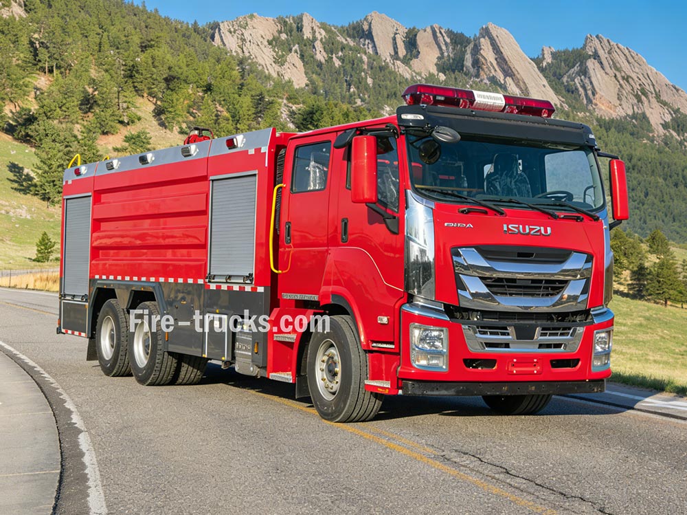
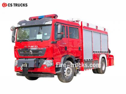
İtfaiye araçları Su temini, basınç oluşturma ve yangın söndürme gibi işlevleri yerine getirmek için birden fazla sistemin koordineli çalışması esasına dayanır. Bu prensipleri anlamak, itfaiye ekiplerinin acil durumlarda etkili bir şekilde çalışmasına yardımcı olur. » Ⅰ. İtfaiye Araçları Nasıl Çalışır: ▪ A. Pompa Sistemi: Yangın Söndürmenin Kalbi: İtfaiye aracının kalbi pompasıdır. Bu yüksek güçlü ünite, araçtaki depodan veya yangın musluğu, göl veya gölet gibi harici bir kaynaktan su çeker ve yüksek basınç altında hortumlar aracılığıyla iletir. En yaygın kullanılan pompa, suyu basınçlandırmak ve hareket ettirmek için dönen bir çark kullanan santrifüj pompadır. İtfaiyeciler, pompa panelindeki bir dizi kol ve gösterge kullanarak su akışını kontrol ederler. Gerektiğinde basıncı ayarlayabilir ve suyu aynı anda birden fazla hortum hattına yönlendirebilirler. Pompa Tipi Özellikler En İyi Uygulama Tek kademeli santrifüj pompa Yüksek akış, orta basınç Genel belediye itfaiyeciliği İki kademeli santrifüj pompa Hacim ve basınç arasında geçiş yapılabilir. Yüksek binalar, uzun hortumlar uzanıyordu. Çok kademeli pompa Çok yüksek basınç Endüstriyel tesisler, köpük sistemleri ▪ Pompanın Temel Parametreleri: › Akış hızı: Dakikada 1.200 - 6.000 litre (modele bağlı olarak) › Maksimum basınç: 1,0 - 2,5 MPa (10-25 bar) › Hazırlık süresi: ≤30 saniye ▪ B. Su Deposu ve Depolama Sistemi: › Yakıt deposu kapasitesi: Araç boyutuna ve tipine bağlı olarak 500 - 1.500 galon (yaklaşık 2.000 ila 6.000 litre). › Tank malzemesi: Korozyona dayanıklı paslanmaz çelik veya kaplamalı karbon çelik › İç bölmeler: Acil durum müdahalesi sırasında su hareketini kontrol etmek için dalgalanma önleyici tasarıma sahip çoklu bölmeler › Dolum süresi: Yangın musluğu veya su çekme yöntemiyle ≤3 dakika › Su seviyesi göstergesi: Depo tarafında görsel gösterge; isteğe bağlı kabin ekranı Tank, genellikle paslanmaz çelik veya kaplamalı karbon çelik gibi korozyona dayanıklı malzemelerden üretilmiştir ve acil durum sürüşü sırasında su dalgalanmasını kontrol eden iç bölme plakalarına sahiptir. ▪ C. Hortum ve Meme Sistemleri İtfaiye araçları farklı işlevlere sahip çeşitli hortumlar taşır: › Yangın söndürme hortumu: 1,5 - 2,5 inç çapında — suyu doğrudan yangın kaynağına iletir. › Besleme hortumu: 4 - 5 inç çapında — hidrantlardan veya diğer pompalardan su taşır › Takviye hortumu: makaraya sarılı küçük çaplı hortum — çim veya araç yangınları gibi küçük yangınlar için kullanılır. Hortumun ucundaki nozul, itfaiyecilerin yangın türüne bağlı olarak basıncı, püskürtme şeklini ve yönünü ayarlayarak su akışını kontrol etmelerini sağlar. ▪ D. Yangın İzleme Cihazı › Su monitörü: Geniş çaplı yangın söndürme için yüksek hacimli su akışı sağlar; sabit veya uzaktan kumandalı olarak çalıştırılabilir. › Kuru toz monitörü: Yanıcı sıvı, gaz ve elektrik yangınlarında kuru kimyasal toz püskürtür. › Kombine monitör: Hem su hem de kuru toz boşaltımı yapabilme özelliğine sahiptir; gerektiğinde ortamlar arasında geçiş yapar. ▪ E. M...
Detaylar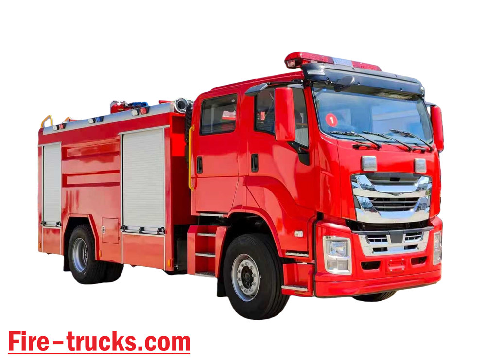
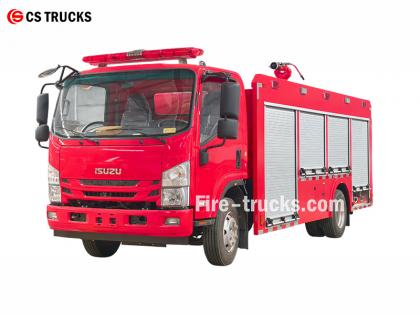
En profesyonel Isuzu İtfaiye Aracı fabrikası olarak, Isuzu NPR su köpüklü itfaiye aracının temel tasarımı, köpüklü yangın söndürme sistemini su tankerli itfaiye aracına entegre ederek hem su hem de köpük püskürtebilen kompozit bir yangın söndürme ekipmanı oluşturmaktır. Bağımsız olarak yangınları söndürebilir; diğer ekipmanlara su veya köpük karışımı iletebilir; ve kurak ve su kıtlığı çeken bölgelerdeki operasyonlar için uygundur. ★ Teknik Özellikler CS Trucks'ın tüm itfaiye araçları, %100 müşteri gereksinimlerine göre üretilmektedir. Kapasite Motor modeli su Köpük Yangın Pompası Yangın Monitörü 2.500 litre ISUZU 4HK1 / 19 0 HP 2.500 litre 500 litre CB10/40 Yangın Pompası PL8/32 2026 resmi ISUZU İtfaiye aracı kabin şasisi kamyonu 2026 orijinal itfaiye aracı şasi çizimi Öğe Isuzu İtfaiye Araçlarının Tasarım Detayları Tasarım Çekirdeği Su tankerli itfaiye aracına köpük söndürme sistemini entegre ederek, hem su hem de köpük püskürtebilen çift amaçlı bir yangın söndürme aracı oluşturur. Özellikleri şunlardır: • Bağımsız yangın söndürme • Diğer ekipmanlara su veya köpük karışımı temini • Kurak veya su kıtlığı çeken bölgeler için uygundur ve çok fonksiyonlu kullanıma olanak tanır. Genel Tasarım Konsepti Atölyelerde ve çevresindeki alanlarda yangın söndürme ihtiyaçlarını karşılamak üzere tasarlanan ve petrol, elektrik ve katı madde yangınlarına karşı gelişmiş yeteneklere sahip olan araç, güvenilirlik, çok işlevlilik ve kullanım kolaylığına önem veren bir şasi ve özel gövde ekipmanından oluşmaktadır. Şasi Seçimi • Kanıtlanmış orta veya ağır hizmet tipi II şasi kullanır. • Zorlu arazi koşullarında hareket kabiliyetini ve çekişi artırmak için dört tekerlekten çekiş önerilir. 2026 YENİ TASARIM ISUZU 700P Su İtfaiye Araçları Temel Sistem Bileşenleri ve Tasarımın Önemli Noktaları 1. Su Tankı ve Köpük Sıvı Tankı • Malzeme: Paslanmaz çelik, korozyona dayanıklı • Önerilen kapasite: Su deposu 3000–5000 litre, köpük sıvı deposu 300–600 litre • Yapısal optimizasyon: İç bölmeler su ve köpük haznelerini ayırır ve bağlantı noktaları aracılığıyla tek su tankı moduna geçiş yapılarak çok amaçlı kullanım sağlanır. 2. Köpük Oranlama Sistemi • Su ve köpük konsantresini %3 veya %6 oranlarında hassas bir şekilde karıştırmak için dengeli basınç oranlayıcı (ana bileşen) kullanır. • Akış veya basınç dalgalanmalarından etkilenmeyen, istikrarlı çıkış gücü; uzman olmayan operatörler için uygundur. • Yerinde köpük takviyesi için harici köpük emme girişi ile donatılmıştır. 3. Boşaltma Sistemi • Yangın pompası: Yüksek verimli, enerji tasarruflu çok kademeli santrifüj pompa, debi ≥ 4 0 L/S • Yangın izleme cihazı: Uzaktan kumandalı, su/köpük püskürtme özelliğine sahip, çift amaçlı izleme cihazı, menzili ≥50 metre, açısı ayarlanabilir. • Esnek çalışma için yangın hortumlarına ve köpük püskürtme nozullarına bağlantıyı destekler. 2026 YENİ TASARIM ISUZU NPR Köpük İtfaiye Araçları Uygulama Senaryoları ve Avantajları Atölyede petrol sızıntısı yangını Son derece uygun; köpük, oksijen izolasyo...
Detaylar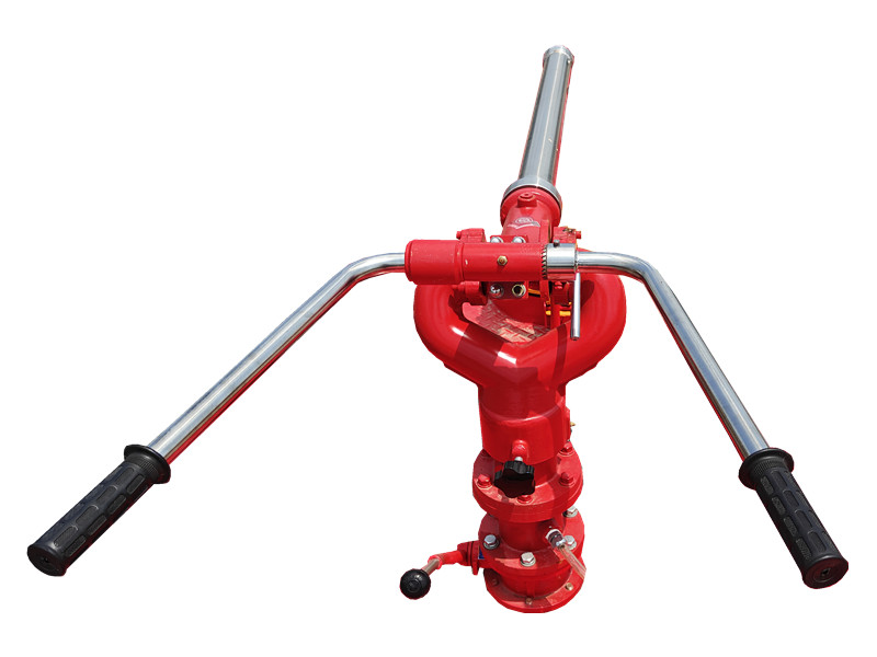
PF5-15 sabit kuru toz monitörü Kuru toz halindeki bu ürün, püskürtme ortamı olarak kullanılır ve sabit bir taban sayesinde istikrarlı püskürtme sağlar. Kimyasal ve depo alanları için uygundur ve yangının erken aşamalarında yanan yüzeyi hızla kaplayarak söndürme verimliliğini artırır. O PF5-15 sabit kuru toz monitörü Sağlam bir yapıya sahip, kullanımı kolay ve uzaktan aktivasyon ve hassas püskürtme için otomatik kontrol sistemiyle entegre edilebiliyor. » Ⅰ. PF5-15 sabit kuru toz monitörü yapı: PF5-15 sabit kuru toz monitörünün özellikleri: ● Tamamen işlevsel; ● Basit ve özgün yapı; ● İstikrarlı performans ve kolay bakım; ● Düşük giriş basıncı; ● Yatay ve dikey kilitleme fonksiyonlarına sahip otomatik tahliye vanası ile donatılmıştır; ● Malzeme: Hassas döküm alüminyum alaşımı; ● Top başlığı: Alüminyum alaşımı. » II. Köpük Tabancası PL24 Özellikler: Model Akış ( kilogram /S ( Menzil ( M ( Nominal çalışma basıncı ( MPa ( Eğim dönüşü ( ° ( Yatay dönüş ( ° ( U×G×Y ( mm ( Ağırlık ( Kilogram ( PF5-15/40 40 ≥42 0.80 -45 ~ +70 0 ~ 360 980x340x550 28.5 » III. Ürün Uygulamaları: PF5-15 sabit kuru toz monitörlü itfaiye aracı PF5-15 sabit kuru toz monitörü testi PF5-15 sabit kuru tozlu yangın söndürme cihazı, uzun püskürtme mesafesi ve geniş kapsama alanı ile hızlı bir şekilde kuru tozlu yangın söndürme bariyeri oluşturabilir. Kimya tesisleri, petrol depoları ve depolama alanları gibi sabit yerler için uygundur ve geniş alanlar için sürekli ve istikrarlı yangın söndürme yeteneği sağlar.
Detaylar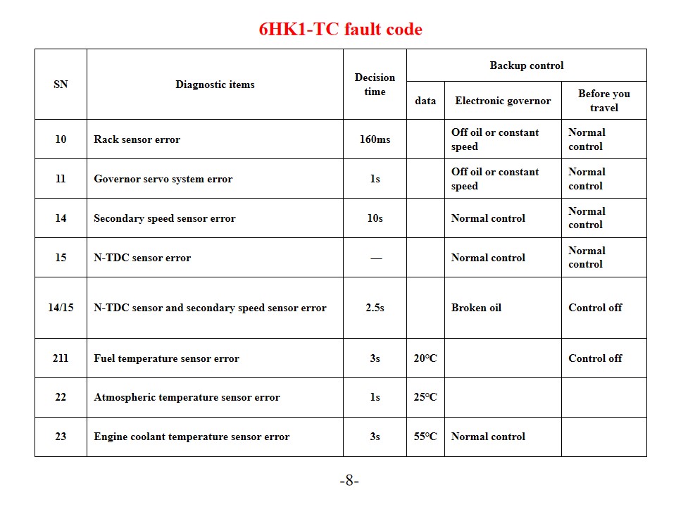
Isuzu 6HK1-TC itfaiye araçları aynı zamanda şu şekilde de adlandırılır: Isuzu kurtarma ve itfaiye aracı Motor Arıza Kodu Teşhisi ve Çözümleri. Isuzu 6HK1-TC motoru, gelişmiş TICS yakıt enjeksiyon pompası elektronik kontrol sistemini kullanır ve ECU (Motor Kontrol Ünitesi) kendi kendine teşhis özelliğine sahiptir. Sistem bir arıza tespit ettiğinde, "MOTORU KONTROL ET" uyarı lambası yanar ve ilgili arıza kodu kaydedilir. Bu hata kodlarının yorumlanması ve çözümlerinin anlaşılması, motor bakım verimliliğini etkili bir şekilde artırabilir. Sık Karşılaşılan Hata Kodları ve Çözümleri P Serisi Arıza Kodları P0101 (Hava Akış Sensörü Devresi Düşük) Motor soğutma suyu sıcaklık sensörünü ve kablolarını kontrol edin. Sensörün güç kaynağı voltajını ve topraklama bağlantısını doğrulayın. Gerekirse ECU'yu veya sensörü değiştirin. P0102 (Hava Akış Sensörü Devresi Yüksek) Yakıt kalitesini ve filtre durumunu kontrol edin. Yakıt sistemini temizleyin. Yakıt basınç regülatörünü, yakıt pompasını ve enjektör devrelerini kontrol edin. P0103 (Hava Akış Sensörü A Devresi Yüksek) Sensör sinyal devresinde kısa devre olup olmadığını kontrol edin. Sensörün çalışma durumunu test edin. Gerekirse sensörü veya ECU'yu değiştirin. Dijital Arıza Kodları 10 (Raf Sensörü Hatası) Raf sensörünü ve kablolarını kontrol edin. Sinyal iletiminin normal olduğunu doğrulayın. 11 (Hız Kontrol Servo Sistemi Hatası) Hız kontrol servo sisteminin çalışma durumunu kontrol edin. İlgili devre bağlantılarını test edin. 14 (Yardımcı Hız Sensörü Hatası) Yardımcı hız sensörünün montaj konumunu kontrol edin. Sensörün sinyal çıkışını test edin. 15 (N-TDC Sensör Hatası) N-TDC sensör bağlantısını kontrol edin. Sinyal doğruluğunu doğrulayın. Sistem bakımı ve önleyici tedbirler SN Teşhis öğeleri Karar verme zamanı Yedekleme kontrolü veri Elektronik vali Seyahate çıkmadan önce 10 Raf sensörü hatası 160 ms Yağsız veya sabit hızda Normal kontrol 11 Vali servo sistemi hatası 1 saniye Yağsız veya sabit hızda Normal kontrol 14 İkincil hız sensörü hatası 10 saniye Normal kontrol Normal kontrol 15 N-TDC sensör hatası — Normal kontrol Normal kontrol 14/15 N-TDC sensörü ve ikincil hız sensörü hatası 2,5 saniye Kırık yağ Kontrol kapalı 211 Yakıt sıcaklık sensörü hatası 3 saniye 20℃ Kontrol kapalı 22 Atmosferik sıcaklık sensörü hatası 1 saniye 25℃ 23 Motor soğutma suyu sıcaklık sensörü hatası 3 saniye 55℃ Normal kontrol Bağlayıcı Terminal No. Sinyal Tel kalınlığı/çapı (Enjektör pompası kablo demeti) SWP 8 terminal Siyah 1 Regülatör aktüatör tahrik voltajı - 1 RM 2 2 Vali devresi GND-1 W/1.2 3 Hedef raf konumu - 1 U1 2 4 Raf konum voltajı G/1.2 5 Vali devresi 5V-1 Y/1.2 6 Yedek N sensörü (GND) BR/1.2 7 Yedek N sensörü (SIG) 0/1.2 8 Aşağı çek B/1.2 SWP6- terminaller Siyah G Regülatör aktüatör tahrik voltajı - 2 R/1.2 10 Hedef raf konumu - 2 L/1.2 11 Vali devresi GND-2 W/1.2 12 Vali devresi SIG-GND BR/1.2 13 Vali devresi 5V-2 Y/1.2 SWP 3- terminaller Siyah 14 Eve topallayarak W1.2 15 Alt bobin (Kullanılmıyor) BY/1.2 Düzenli ba...
Detaylar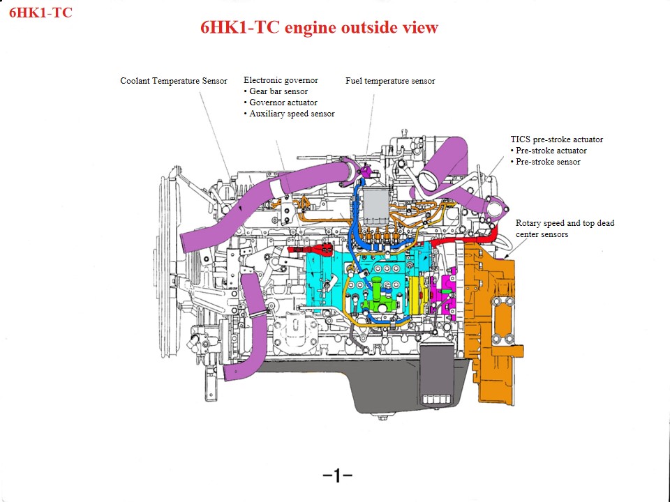
Isuzu 6HK1 İtfaiye ve Kurtarma Araçları aynı zamanda şu şekilde de adlandırılır: Isuzu itfaiye aracı , Bir Isuzu kurtarma itfaiye aracının motoru aşırı ısınırsa, öncelikle aşağıdaki alanlar kontrol edilmelidir: 1. Soğutma sistemi: Hasarlı fan, tıkalı radyatör, hasarlı termostat veya yetersiz soğutma sıvısı gibi sorunlar motorun aşırı ısınmasına katkıda bulunabilir. 2. Yağ kalitesi ve miktarı: Yağ kalitesinin düşük olması veya yetersiz yağ kullanımı da motorun aşırı ısınmasına neden olabilir. 3. Silindir patlaması, silindir gömleği çatlakları veya silindir gömleği yırtılması gibi mekanik arızalar da bu olaya neden olabilir. Ağır hizmet tipi dizel güç aktarma sistemi olan Isuzu 6HK1 motorunun bakımı için teknik özelliklere sıkı sıkıya uyulması gerekmektedir. Başlıca noktalar şunlardır: 1. Yapısal Anlayış ve Sökme-Montaj Özellikleri Krank Mili-Biyel Kolu Mekanizması Silindir gömleği gevşek geçmeli bir tasarıma sahiptir ve sökme ve takma sırasında düşmesini önlemek için özel aletler gerektirir. Standart boşluk 0,122–0,156 mm'dir. Pistonun dış çapı dar bir toleransa sahiptir (114,894–114,909 mm). Montaj sırasında, piston segmanının açılma yönüne ve "üç boşluğun" (uç boşluğu, yan boşluk ve arka boşluk) ayarlanmasına dikkat edin. Alt karter tek parça bir yapıdır ve deformasyonu önlemek için bakım sırasında kaldırılmalıdır. Zamanlama Sistemi Hizalaması Şanzıman montajı sırasında, krank mili dişlisi ve avara dişlisi işaretlerini hizalayın. Eksantrik mili B işareti silindir kapağı yüzeyiyle aynı hizada olmalıdır. Motor, birinci silindirde sıkıştırma üst ölü noktasında olmalıdır. Yakıt enjektör pompasını takarken, zamanlama göstergesini konektör üzerindeki S noktasıyla ve enjektör avans işaretini pompa gövdesi göstergesiyle hizalayın. • Doğrusal DC motor, kontrol ünitesinin çıkış sinyali doğrultusunda bobini yukarı ve aşağı hareket ettirir. • Bobin tertibatına takılan bağlantı çubuğu, bobinin yukarı ve aşağı hareketini bağlantı bloğuna iletir ve bağlantı bloğu, kremayerin ucuna monte edilmiştir. Bağlantı bloğunun itmesiyle kremayer, enjekte edilen yakıt miktarını değiştirmek için sola ve sağa hareket eder. Bobin tertibatı yukarı hareket ettiğinde, bağlantı kremayeri iterek yağın yönünü artırır; tersine, bobin tertibatı aşağı indiğinde, kremayer yağın yönünü azaltacak şekilde hareket eder ve kolonun işlevi, dikey hareketi kremayerin dikey hareketine dönüştürmektir. • Bakır blok, bağlantı bloğunun üst kısmına monte edilerek bir dişli sensörü oluşturur. Dişli sensörü, dişli hareketini algılar ve bu değeri kontrol ünitesine geri iletir; böylece gerçek dişli hareketi ile hedef dişli hareketi arasındaki fark sıfıra yaklaşana kadar sürekli olarak karşılaştırılabilir. Bu işlem, kontrol doğruluğu ve tepki süresi açısından çok önemlidir. 2. Sistem Bakımında Dikkat Edilmesi Gereken Önemli Noktalar Yağlama ve Soğutma Sistemi Yağ değişim aralığı: Mineral yağ: her 5.000 kilometrede veya altı ayda bir; sentetik yağ: 8.000-10.000 kilometre. Soğutma suyu girişi kademeli bir...
Detaylar
Lütfen okumaya devam edin, haberdar kalın, abone olun ve düşüncelerinizi bizimle paylaşmanızı bekliyoruz.

 IPv6 Ağ Desteklendi

 Türkçe
 English
 français
 Deutsch
 русский
 italiano
 español
 português
 Nederlands
 العربية
 日本語
日本語 한국의
한국의 Melayu
 ไทย
ไทย Tiếng Việt
 Indonesia
  中文
中文 қазақ
қазақ Filipino
 မြန်မာ
 српски